Thank you very much, Current!
I meant that I have four trafos for two amps and two psu and I would put two trafos in a box with psu board and connect them to an amp box, and the same for other channel....
In that situation, two PSU cases (or one single case) would be fine. Each PSU case supplying one amplifier channel.
Regards,
currentflow
In that situation, two PSU cases (or one single case) would be fine. Each PSU case supplying one amplifier channel.
Regards,
currentflow
Exactly! And in this case, I was considering how to safety earthing both cases....
Maybe connecting mains earth to both and amp's 0 volt to earth trough a ground loop breaker like the following?
Earthing (Grounding) Your Hi-Fi - Tricks and Techniques
Regards!
Quite interesting post here about Symasym without coupling caps:
Google Translate
Did somebody else try?")
Google Translate
Did somebody else try?
probably lot's of people have tried.Quite interesting post here about Symasym without coupling caps:..............Did somebody else try?
Take any AC coupled Power Amplifier and connect it to an AC coupled output stage of the source equipment.
You now have doubled the DC blocking capability of the Source to Amplifier connection.
There is absolutely no benefit in double blocking the connection.
The solution is easy.
Go into both pieces of equipment and determine which blocking capacitor is doing most harm to the resulting sound quality. Short out that "not so good" blocking capacitor.
That solution is quite different from "Symasym without coupling caps".
Hello!
I want reduce the AC-gain of about 27dB what changes should I do with amplifiers (symasym 5_3), understand the characteristics remain almost the same?!
Thanks and cheers
Mike B describes this in the Symasym webpage at:
http://http://www.lf-pro.net/mbittner/Sym5_Webpage/symasym5_3.html
He writes: If the gain is too high because symasym is driven from preamp, R30 can be increased from 499ohms to 1k, but in this case R16/19 (22 or 33 ohms, not on schematic, REs to Q1/2) are required to keep feedback at same level and symasym stable.
All that said low-understand?!Mike B describes this in the Symasym webpage at:
http://http://www.lf-pro.net/mbittner/Sym5_Webpage/symasym5_3.html
He writes: If the gain is too high because symasym is driven from preamp, R30 can be increased from 499ohms to 1k, but in this case R16/19 (22 or 33 ohms, not on schematic, REs to Q1/2) are required to keep feedback at same level and symasym stable.
I ask for a little explanation of the changes of the schematic.
Where are the resistors R16/R19 and etc.,....?
thanks and regards
Last edited:
All that said low-understand?!
I ask for a little explanation of the changes of the schematic.
Where are the resistors R16/R19 and etc.,....?
thanks and regards
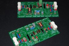
These resistors are not on schematics, but there are premade connections for them only on the PCB board version 5.3.
Attachments
probably lot's of people have tried.
Take any AC coupled Power Amplifier and connect it to an AC coupled output stage of the source equipment.
You now have doubled the DC blocking capability of the Source to Amplifier connection.
There is absolutely no benefit in double blocking the connection.
The solution is easy.
Go into both pieces of equipment and determine which blocking capacitor is doing most harm to the resulting sound quality. Short out that "not so good" blocking capacitor.
That solution is quite different from "Symasym without coupling caps".
Thank you very much Andrew! Wise advice!
In my case, having a B1 with double output (main amp and subwoofers amp connected to it) I will short the cheap mks2 wima in symasym...
Thank you again!
Regards!
Andrea
The DCB1 is a DC coupled source.
You should not bypass the only DC blocking capacitor.
If you have the experience to recognise the pitfalls of converting an AC coupled system into a mixed AC and DC coupled system then go ahead and make that informed decision.
The B1 is an AC coupled source and with that you can safely bypass the DC blocking cap in the Symasym.
probably lot's of people have tried.
Take any AC coupled Power Amplifier and connect it to an AC coupled output stage of the source equipment.
You now have doubled the DC blocking capability of the Source to Amplifier connection.
There is absolutely no benefit in double blocking the connection.
The solution is easy.
Go into both pieces of equipment and determine which blocking capacitor is doing most harm to the resulting sound quality. Short out that "not so good" blocking capacitor.
That solution is quite different from "Symasym without coupling caps".
Andrew is right (as usual) this is a very nice idea and often can be a huge improvment where ever is possible to do so .
and why I have been advocating dual inputs to Power amps and dual outputs from Sources.Andrew is right (as usual) this is a very nice idea and often can be a huge improvement where ever is possible to do so .
Going back to Jens' Leach clone where he had installed 3pin input (0.1" sil) for the PCB.
The 3 pins offered AC coupled, or "test position", or DC blocker bypass, by just moving a 0.1" shorting plug. Takes near zero PCB space and near zero cost, for great flexibility in operation.
The B1 is an AC coupled source and with that you can safely bypass the DC blocking cap in the Symasym.
My case!
Thanks, Andrew!
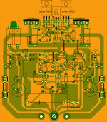
got this from M.Bittner site. same version with last thread why so many to92?
regards,
joel
I´d say nine,just as it should be....
he he
It could be an optical illusion,the way that they are spreaded on a pcb. I thougt the same thing before i counted them one by one. I have done SymAsym 5.3 and first thing i have noticed that is different on your pcb than on my is two diodes between E and C of output transistors. MURS120 exists on your pcb and on my they are not provided. It works anyway!
may be my eyes are just tired
regards,
joel
It could be an optical illusion,the way that they are spreaded on a pcb. I thougt the same thing before i counted them one by one. I have done SymAsym 5.3 and first thing i have noticed that is different on your pcb than on my is two diodes between E and C of output transistors. MURS120 exists on your pcb and on my they are not provided. It works anyway!
got this from M.Bittner site. same version with last thread why so many to92?
regards,
joel
I couldn't locate where that pcb is from.
 Can someone direct me to the site where the pcb above sold? Thanks.
- Home
- Amplifiers
- Solid State
- Explendid amplifier designed by Michael Bittner, our MikeB