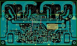
PCB based on Rudi Ratlos and others.
..... Hi radio , I have made some cosmetics on Rudi's PCB wich is the best PCB until now , congrat's to Rudi , I like red colour , nice PCB's . I have tryed to layout for single side , to be available everyone who intend to do this variant .....")
Regards Alex .
..... Hi radio , I have made some cosmetics on Rudi's PCB wich is the best PCB until now , congrat's to Rudi , I like red colour , nice PCB's . I have tryed to layout for single side , to be available everyone who intend to do this variant .....
Regards Alex .
Attachments
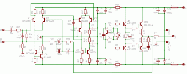
Hi there, reading this topic which interests me because pcb design is something tricky, I just post a link to another thread. The last post there has my schematic and pcb attached to it...
Anyone in to comment?
Keep in mind this circuit lacks an OPS yet. The one present is just a dummy OPS (single EF stage) not to have the VAS directly returned to the IPS (GFBL).
http://www.diyaudio.com/forums/soli...ogy-construction-troubles-36.html#post2700402
Thnx
Olivier
Anyone in to comment?
Keep in mind this circuit lacks an OPS yet. The one present is just a dummy OPS (single EF stage) not to have the VAS directly returned to the IPS (GFBL).
http://www.diyaudio.com/forums/soli...ogy-construction-troubles-36.html#post2700402
Thnx
Olivier
Alex, I do not have any objectives against publishing the Gerber files, a PDF document, ...
I have just closed the TO-3 SYMASYM group-buy and will not offer the PCBs again.
(There is another very interesting project waiting for me)
Your layout looks very good to me, but I did not check every track.
Best regards - Rudi_Ratlos
I have just closed the TO-3 SYMASYM group-buy and will not offer the PCBs again.
(There is another very interesting project waiting for me
)Your layout looks very good to me, but I did not check every track.
Best regards - Rudi_Ratlos
here is a thing ...
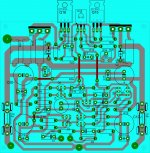
Dear Allex even though i think of you as a very hard working guy and your efforts to share pcbs for many designs exist in the forum worth really a lot there is something that i have to tell you ....
I think that you will learn a lot more about pcb and amplifiers if you construct and listen to the amplifiers that you design pcbs for.
i am not trying to underestimate your work ... on the contrary i am trying to enhance your effort ( since i never managed to follow all the design rules for even very low part count amplifier in a single layer ) may be someone like you more talented or skilled after all manages it ...that will be inovation and will put a lot in amplifiers
if a patern like that is made may others will follow and we all learn and gain something better from a joined effort ....
for example and for the above pcb
--- there is no star ground ( i am not the one to decide if needed or not but the question to be answered by experts will be a joy )
--- Ground is "flooding" arround the pcb
--- rails ar too long ( ideally could be designed in the midle or supplied elsewhere eventhough not proctical or symmetric looks )
--- curent sources /mirrors should e kept as close is possible to the LTP while no "hard currents" is crossing between them
--- i would never cross a trace down under a 5mm pitch capacitor ...especially if this is one is doing something importand
--- then i think i could keep regulators seperated in some side area and away from small signal areas ...
finally i cannot tell if this is possible to be done in a single layer pcb and if any or allthis paterns applied will make the amplifier any better and then again how much better ....this is for real experts to answer ...
kind regards sakis
Alex mm, why did you do any PCB with one pair of output transistors MJL3281A/MJL1302A (2SC2922/2SA1216) like the schematic, because I need such PCB a power supply for Us= +/-36Vdc?!..... Hi radio , I have made some cosmetics on Rudi's PCB wich is the best PCB until now , congrat's to Rudi , I like red colour , nice PCB's . I have tryed to layout for single side , to be available everyone who intend to do this variant .....
Regards Alex .
thanks and cheers

Attachments
Last edited:
here is a thing ...
Dear Allex even though i think of you as a very hard working guy and your efforts to share pcbs for many designs exist in the forum worth really a lot there is something that i have to tell you ....
I think that you will learn a lot more about pcb and amplifiers if you construct and listen to the amplifiers that you design pcbs for.
i am not trying to underestimate your work ... on the contrary i am trying to enhance your effort ( since i never managed to follow all the design rules for even very low part count amplifier in a single layer ) may be someone like you more talented or skilled after all manages it ...that will be inovation and will put a lot in amplifiers
if a patern like that is made may others will follow and we all learn and gain something better from a joined effort ....
for example and for the above pcb
--- there is no star ground ( i am not the one to decide if needed or not but the question to be answered by experts will be a joy )
--- Ground is "flooding" arround the pcb
--- rails ar too long ( ideally could be designed in the midle or supplied elsewhere eventhough not proctical or symmetric looks )
--- curent sources /mirrors should e kept as close is possible to the LTP while no "hard currents" is crossing between them
--- i would never cross a trace down under a 5mm pitch capacitor ...especially if this is one is doing something importand
--- then i think i could keep regulators seperated in some side area and away from small signal areas ...
finally i cannot tell if this is possible to be done in a single layer pcb and if any or allthis paterns applied will make the amplifier any better and then again how much better ....this is for real experts to answer ...
kind regards sakis
It`s already a miracle to me how Alex finds the time to do all those really very nice and very well thought out PCB Layouts. I`ve tried to make own layouts, so I do know how much time and effort this can cost even for relatively "simple" schematics.
Now also building, debugging, listening, comparing and revising this multitude of different amp and PCB Layouts, IMO would require a fulltime effort if that would be enough at all. I`d say that`s enough work for a team of engineers in a pro audio company.
As for Your suggestions "improving" the layout. Just try it for yourself, it`s not complicated nor expensive. There are some nice free PCB CAD programs out there. It`s quite straightforward, all You need is a lot of patience.
For example grab the schematics of Rudi`s amp for which Alex has done the layout above. Don`t "cheat" and don`t look at Alex`s layout. Then try for yourself and see what You come up with. You`ll realize very quickly that it is, as always, all about making compromises and that there is no "perfect" layout. Inevitably You`ll end up with various choices. The question which one will be "better" puts You straight back to square one. To actually build all those choices and to compare them would be an incredible tedious procedure.
Of course it could be done but I doubt that many DIYers do have the time for this.
will this be ok to you?
Alex mm, why did you do any PCB with one pair of output transistors MJL3281A/MJL1302A (2SC2922/2SA1216) like the schematic, because I need such PCB a power supply for Us= +/-36Vdc?!
thanks and cheers
Attachments
Need better example
Could you please post your PCB Layout and so I can get a better idea of your recommended techniques. I am familiar with the basic procedure and look forward to learning more.
A completed layout would be of great help.
here is a thing ...
I think that you will learn a lot more about pcb and amplifiers if you construct and listen to the amplifiers that you design pcbs for.
kind regards sakis
Could you please post your PCB Layout and so I can get a better idea of your recommended techniques. I am familiar with the basic procedure and look forward to learning more.
A completed layout would be of great help.

about resistor...
I could not find a coil in my library so I used a 5 watts resistor as substitute.my schematic and board layout is not yet final especially the names in my schematic and tracks in my board layout.if i have nothing to do in ofc. may be tomorrow I could post the foil pattern.
Thank drowranger to PCB layout!
Beautifully designed PCB!!
Schematic according to which the labels (numbers) components??
Since the above schematic has given the other numbers!?
thanks and cheers !
I could not find a coil in my library so I used a 5 watts resistor as substitute.my schematic and board layout is not yet final especially the names in my schematic and tracks in my board layout.if i have nothing to do in ofc. may be tomorrow I could post the foil pattern.
symasym5
schematic based on post 36
Thank drowranger to PCB layout!
Beautifully designed PCB!!
Question: At what schematic you put labels (numbers) components??
Under this schematic (see dshematic)) are not!?
thanks and cheers !
schematic based on post 36
radio, why don't you just visit SymAsym5 - Project grep those
and be done with it?
Code:
The files for making boards:

    Eagle board files:  Eagle 4.15 sym5_3 board files download (zipped) 37kb
    File for printout:   600dpi symasym5_3 monochrome bitmap (zipped) 45kb
    The upper layer is misused for showing the wire jumpers !
Files for production: Gerber files (zipped) 37kb Excellon drill files (zipped) 2kbHi all!
Good people want to help me about this amplifier circuit description symasym 5_3.
Amplifier works perfectly but the principle of operation is not clear to me!
So if you are able to give some description, ...
A big thank you in advance!
P.S.
Chinese proverb says: "Do not give man a fish to eat, but the science of man catches fish"!
Why?, because he wants to be spoon fed.
With a surname like that, I would keep my comments to myself
Hi to everybody!
First of all, sorry for my bad english....
I wanted to ask advice for grounding my Symasym: I'm going to build a dual mono Symasym v.5_3 and I was planning to build like this:
two trafos with single secondaries ---psu board --- amp board
putting the trafos and psu's in a separate case (or two separate cases) from two small aluminum enclosures for amp boards....
As I understood, it's very important that I ground the heatsink and amp case to avoid picking up rf noise....
What is, in your opinion, the best way to ground psu case and amp case avoiding ground loops?
Would you use a ground loop breaker connected to heart in the psu case and connect this also to amp ground and amp case?
Thank you so much!
Regards!
P.S. For example, if I connect earth to psu case and amp case, but put two ground loop isolators in the amp cases for connecting earth to 0 volt point, could it work?
Last edited:
Hi Porfido,Hi to everybody!
I'm going to build a dual mono Symasym v.5_3 and I was planning to build like this:
two trafos with single secondaries ---psu board --- amp board
putting the trafos and psu's in a separate case (or two separate cases) from two small aluminum enclosures for amp boards....
I wouldn't recommend two cases for the transformers if they have single secondaries. If there is any chance of one becoming unplugged at either its input or output while the amplifier is operating, losing one rail could have disastrous consequences. Best keep the transformers together in a single case.
Regards,
currentflow
Hi Porfido,
I wouldn't recommend two cases for the transformers if they have single secondaries. If there is any chance of one becoming unplugged at either its input or output while the amplifier is operating, losing one rail could have disastrous consequences. Best keep the transformers together in a single case.
Regards,
currentflow
Thank you very much for your feedback, Current!
I meant that I have four trafos for two amps and two psu and I would put two trafos in a box with psu board and connect them to an amp box, and the same for other channel....
Regards!
Last edited:
- Home
- Amplifiers
- Solid State
- Explendid amplifier designed by Michael Bittner, our MikeB