Well my dear Michael, this is just my way to say thanks to you, to Hugh and Graham.
In special we had an unforgeatable fun, sending audio comparisons, and many test steps procedure together.
And i thank you because you gave me this opportunitty to see one excelent amplifier borning.
You welcome ....Your Majesty
regards,
Carlos
In special we had an unforgeatable fun, sending audio comparisons, and many test steps procedure together.
And i thank you because you gave me this opportunitty to see one excelent amplifier borning.
You welcome ....Your Majesty
regards,
Carlos
Attachments
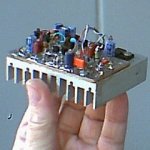
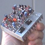
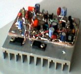
My version will be ready in two weeks. I planned with two pairs of output devices, and with +/-40V PSU. The PCB design is ready. It was not easy, due it takes all the necessary parts except the rectifier bridge. So finally it's 12x10cm, double sided version, with two 22000uF BC capacitors.
I will use MJL21193/94 outputs, and MJE15030/31 drivers. For VAS I get some 2Ns, which used by Michael, and the input is BC556B.
sajti
I will use MJL21193/94 outputs, and MJE15030/31 drivers. For VAS I get some 2Ns, which used by Michael, and the input is BC556B.
sajti
That is great Satji.... having images send us, step by step or finished work...
You decide...but i am very curious about those things.
I will produce the Symassym 5 too.
Good news, i am sure Michael will be happy with one more doing this amplifier.
He told me that he feel good when he has the chance to share this amplifier with more guys.
regards,
Carlos
You decide...but i am very curious about those things.
I will produce the Symassym 5 too.
Good news, i am sure Michael will be happy with one more doing this amplifier.
He told me that he feel good when he has the chance to share this amplifier with more guys.
regards,
Carlos
MikeB said:Hi Sheldon,
The 220uf-cap after the feedbackdivider is a normal electrolytic,
(i used 470uf,16v here) can be a low voltage type, with plus to gnd.
It gets charged with ~12mv (depending on the hfe of the input-bjts)
Mike
Thanks Mike. As I said, my experience is limited. I've only built one tube circuit that was entirely from a general schematic that I modified a bit. Along the way, I looked a a large number of similar circuits and various feedback applications. In those amps, some sort of feedback compensation caps are fairly common. But the great majority were caps across a feedback resistor, either to shunt high frequency noise or to shape the output. Your caps are in series with the feedback resistor to ground. Beyond just soldering in the right part in the right orientation, I'm trying to figure out what everything is doing there. The small cap, I get. But I'm a bit puzzled by how the larger cap interacts with the output and base, as there is no direct connection between the divider and ground. Do you have a handy reference I could check that covers the principles involved in this particular application?
And Carlos, wow that's a nice article you put together. By generalizing the few specific references to the Symasym, it would make a nice primer for anyone putting together a typical ss amp. Maybe that should be a sticky thread.
BTW, I only soldered up maybe a dozen boards over the last year or so(way behind your thousands), but I've already made most of those mistakes. Let the magic smoke out of some LM 3xxx chips by reversing the ps polarity. And lost smoke from some power supply transistors more than once by inadvertantly shorting the output. And wired things wrong, between looking at a schematic, laying out real parts, and trying to keep track of the top and bottom view.
Sheldon
Hi Sheldon,
The cap in paralell (22pf) to the feedbackresistor is a "phaseshifter",
partially reverting the phaseshift introduced by the circuit from
input to output. It's mainpurpose is avoiding overshooting.
The other cap in series with the 499ohm, is a DC-blocking cap.
It has 2 functions, the first is to reduce gain down to 1:1 for DC,
enabling the whole openloopgain to feedback for DC.
The second is, by increasing the 499ohms to infinite for DC, the
inputresistance of the -input of diffamp becomes 22k at DC, the
same as on +input. This results in identical inputoffsets on both
sides of the inputpair, again greatly reducing DC-offset at ouput.
Or did you mean the 330pf in vas to gnd ?
Sajti, good to hear from your progress, the MJL21193/4 are nice transistors !
One thing i did not understand, most asymetrical inputs use pnp-devices, why ?
Aren't npn's more linear ?
Mike
Thanks Mike,
I'll chew on that. The DC block seems the obvious answer. In fact, I probably wouldn't have given it much thought if it were a non polarized cap. What has me confused is using a polarized cap, from which I inferred that the total voltage across the cap is always oriented one direction. But as the signal from the output swings =/- up to 36V, I didn't see how that could be the case. I was trying to imagine operation that doesn't put a reverse polarity across that cap. Is it just that the voltage drop the cap sees is low enough not to matter?
Sheldon
The point is, you need a very low frequency to get this cap charged
in reverse polarity. Typically it is charged with ~12mv and creates
an offset with this voltage to gnd for the 499ohm-resistor.
But the inputcap avoids entering that low frequencies into the amp.
I can show curves for that later. A nonpolarized cap is necessary if
it's not sure with which polarity this cap get's charged.
And i have heard that an electrolytic can be charged with reverse
polarity with low voltages.
Mike
Ok, I think I get it. If I can restate what you said: There is a slight offset that the feedback input is riding on. The feedback signal averages to zero so, as long as the frequency is high enough (controlled by the input cap), there will remain a slight net charge across the cap at any given point in time.
Final check then, and my apologies if I seem thick headed. I interpret your initial answer such that the cap should be oriented with the + lead to ground. But I note that on the first page of the thread, Carlos showed some of what I assume are spice outputs. In the voltage output, it looks like +27mv at the base of the transistor/connection to the cap. If I understand your explanation correctly (not a given yet), that would seem to indicate that the cap should be placed with the - lead to ground. On the other hand, the only current path I see is through the base to the negative rail, which would seem to imply a slight negative charge on the base, and would be consistant with your advise on the cap. Which one have I got wrong, or is the - sign there and just too hard to read?
And many thanks for your gracious and very prompt answers.
Sheldon
Hi Sheldon,
You got it correct !
the minus is hard to see, it's -26.96mv, i don't know from which amp
i remember the -12mv... The basecurrent flows through the 22k to the
ouput, this creates the -27mv. So, the -pin must go to gnd.
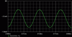
I attached a shot out of sims, 30hz, full power, you see that the
charge of the cap keeps its polarity. It's a 470uf, so it seems a good
choice to use the bigger 470uf instead of the 220uf...
At 10hz it looses the polarity, but who does play a 10hz at these
powerlevels ?
Mike, not yet sleeping...
Attachments
- Home
- Amplifiers
- Solid State
- Explendid amplifier designed by Michael Bittner, our MikeB


