I have a digital oscilloscope with a a function generator and a variety of parts and loads available if someone wants to instruct me.
Connect the function generator to the amps input, and a suitable load to the amps output and connect the scope across the load. Set the generator to a sine wave at 1KHz. Adjust the generator or the amps volume control so that you see a sine wave on the scope. Set the level for a low power level of about a watt. This will be 2.83 volts RMS with an 8 ohm load (8 volts peak to peak). If your scope has voltage measurement functions measure and record this voltage. You should be able to change the frequency of the function generator but the amplitude should remain constant. As you increase the frequency into the 15 to 50KHz region the amplitude should drop. Record the frequency at which the output voltage drops to .707 times its original value. This is the upper 3db point. Repeat the proceedure in the 15 to 50 Hz region.
It is possible to measure the OPT by itself using the same proceedure but you need a signal source that can put out several volts. A solid state amp with good frequency response (way past the transformer being measured) can be used to boost your generator. You connect the source to the transformer primary through a resistor equal to the primary impedance. Attach a resistor equal to the secondary impedance across the secondary with the scope across it. Set the amp for a strong unclipped sine wave and repeat the frequency measurements outlined above.
I can't understand how Ampilo have got it so wrong.
Although I have never tried them Amplimo is a Dutch toroidal transformer maker with a good reputation. We are talking about Antek which is a US based distributor of Chinese transformers.
I will steer clear of their opts and most of their high voltage transformers.
I have decided that their transformers are well made. They are probably well designed and certainly stout enough to deal with my typical overloading. It seems that whoever is specifying these things is NOT familiar with tube amps and probably never made one! There needs to be some better documentation too.
I have a pair of 4TK400's (although I only measured one of them) and several other smaller ones. The big ones are slated for a monster P-P amp with Plitron OPT's. I need more than 475 volts so I will probably resort to the old Tektronix trick of stacking isolated power supplies.
I just happened to have a 8200 ohm and 910 ohm resistor and a pair of 5.1v zeners to whip together a probe.
This may be OK but I found that some sound cards have a significant input capacitance. I found that resistors in this range led to extra rolloff. I had to reduce my values by a factor of 10 or more. At first I used a 10K pot and set it for good level into the sound card. I got about 1 db better HF response by using a 500 ohm pot (thats just what I had). Fixed resistors are a better choice since a pot could lead to a blown sound card if set wrong.
Ditto on the EMU 1212. I have a 1212 and an 1820 (both Ebay minimum bids). I have used them both for recording but neither worked right with my audio analyzer software. The 1820 has a phono stage built in so I have been copying my vinyl onto my hard drive at 2496.
.I am a little confused by these two statements. I wish to measure the OPT by itself, outside of my amplifier like you suggest in the first paragraph, but in the second you imply that a low impedance input will not account for the capacitive loading of the trafo
Measuring the transformer by itself tells you how it would work in an ideal situation. It does not tell you how it will work in your amp. Since every amp design is different measuring a transformer in one amp does not say much about how it will work in another. The plots given on Antek's web site is likely measured with a signal generator it shows a 2 db loss at 20 KHz on the OPT that I looked at, which is the best that it could ever do, so I didn't buy it. This is probably how Hammond can specify 20 Hz to 20 KHz +/- 1db on the 1628SE but every one who uses it finds a much bigger rolloff.
Every transformer has distributed capacitance and inductance in its windings. The specifications are usually measured by driving it with its specified impedance. Unfortunately that is not how it is used. A triode amp in class A will drive the transformer with a lower plate impedance than its rating resulting in better performance than the same transformer driven with a pentode which has a much higher plate impedance. NFB is often used with pentodes to lower their plate impedance.
"I wish to measure the OPT by itself, outside of my amplifier like you suggest in the first paragraph, but in the second you imply that a low impedance input will not account for the capacitive loading of the trafo."
George beat me to it.
And as he says, an amplifier will get better freq. response than the OT test alone indicates due to the lower driving impedance of the typical amplifier output stage (particularly Schaded ones). But this does not come for free, the amplifier has to drive all the shunt capacitance current to overcome it, and this causes HF distortion in the amplifier. So I like to have the OT response alone, so as to know what tradeoffs are occuring.
The series input resistor (for OT alone testing) is the key for matching to the xfmr input Z to do an isolated xfmr response test. Just using the xfmr on the output of the amplifier alone drives it with a lower Zsource, which hides the xfmr's internal shunt capacitance effects. Especially with an amplifier using Schade feedback(s).
At the high frequency end, you will typically find a voltage response peak shortly before plummeting down at a little higher frequency. This is the internal resonance of the primary. This is where shunt capacitance Cshunt and leakage inductance Lleak form a resonant circuit. Fresonant = 1/(2pi*SQRT(Lleak*Cshunt)). If this xfmr is really resonating at 6 KHz, as it appears, and since Lleak is usually much smaller in a toroid design, this would indicate something like 300 times as much shunt capacitance as a normal audio xfmr (Fresonant more like 50 KHz or above for high class ones).
Power transformers are preferred to have high internal shunt capacitance since it helps neutralize the primary inductance magnetizing current (improved power factor). Also, its far cheaper to purchase a winding machine that only does random winds which give this high distributed capacitance. For audio, it takes a progressive wind capable winder machine to eliminate the shunt capacitance. These are far more expensive machines, but once you have one, it takes no longer to wind an xfmr in progressive mode than in random mode. I'm wondering now about all those cheap Chinese amplifiers out there that have toroid OTs.
Last edited:
At the high frequency end, you will typically find a voltage response peak shortly before plummeting down at a little higher frequency. This is the internal resonance of the primary. This is where shunt capacitance Cshunt and leakage inductance Lleak form a resonant circuit. Fresonant = 1/(2pi*SQRT(Lleak*Cshunt)). If this xfmr is really resonating at 6 KHz, as it appears, and since Lleak is usually much smaller in a toroid design, this would indicate something like 300 times as much shunt capacitance as a normal audio xfmr (Fresonant more like 50 KHz or above for high class ones).
I have found that when I have used power toroids, if you wire the primaries in one direction you get the behaviour you describe here out at about 60khz, you also get falling response below about 150hz to boot.. If you switch the direction , both of these issues almost disappear, but high frequency response starts falling a little earlier. Just my observation for what it is worth.
I once used a mains toroidal as a phase splitter with some succcess, though with the 1:1+1 ratio interwinding capacitance made it difficult to avoid a rapidly falling response above 20khz.
Shoog.
Geez, you guys! I can't keep up with this thread! Some of us have to work between reading posts...
Thanks for all the great and interesting information. Hopefully I can measure these soon.
I will measure connecting forward and backward out of respect for Shoog, but I will have to measure without an amplifier if I can, since it isn't built yet. Later, perhaps I will do that too. Good educational process anyway.
Those potted Antek OPT sure are large....
Chinese? Geeez. And I thought it was just some guy in NJ with a toroid winder and nothing better to do.
I don't know that for a fact, but that's what was reported on this forum. A friend who spoke to John on the phone told me that John himself was from somewhere in Asia (Viet Nam?) and the transformers were wound in China. The same guy sells (or used to sell) Par-Metal enclosures. They are nice for amp and equipment building. No clue where they are made.
George beat me to it.
And as he says, an amplifier will get better freq. response than the OT test alone indicates
Not always. Sometimes an amp, especially a pentode amp with minimal feedback may be worse than the transformer alone. That seems to be the case here based on Anteks data.
Sometimes the results don't always make sense. I bought a truck load of surplus P-P OPT's that were designed for guitar amps about 10 years ago. The spec sheet says "80VA, response 80 Hz to 4KHz". I have taken them apart and found no interleaving at all and laminations typical of a power transformer (thick). One half primary is wound first, then the secondaries, then the other half primary with thicker wire to compensate for the longer length.
I bought these cheap to make guitar amps, but I discovered that they sounded real good in a HiFi amp. So good that I have used them in most of my P-P amps including the 300Beast. The odd thing is that the measured frequency response varies greatly with application. The 300Beast is a zero feedback P-P amp using 300B's biased hot so they remain in class A up to about 14 watts. Clipping is about 25 watts. The upper 3db point is about 28KHz. The same transformers are used in a Simple P-P board using EL84's running with 320 volts on the screens and 420 volts on the plates (30 watts at clip). No local feedback, and 5 db of GNFB. The upper 3db point is 65KHz and distortion at 1KHz 1 Watt is 0.18%. I would expect the 300Beast to show better numbers due to the low plate impedance of the hot 300B's.
I have noticed that these transformers show higher distortion at higher frequencies, maybe 1 to 2% at 10 KHz, and some amps like the red board will crank out 100+ watts at 1KHz but only 25 watts at 20 Hz due to saturation, but the power drops off at the high end too. I can get 60 watts at 10KHz but only 30 watts at 20KHz. The plate voltage becomes quite unbalanced at the frequency extremes especially at higher powers.
I have noticed similar behavior when using power (mains) toroids for OPT's. Some work, some don't, but the ones that do work lose their balance at the frequency and power extremes. If the Antek OPT's are wound like power toroids I would expect similar behavior.
I have a couple of Antek HV toroidal power transformers. I haven't used them yet. What I hear here about the output transformers makes me hesitate to try them. I do have a pair of Amplimo toroidal transformers (the low-priced series) waiting for the right project. Can anyone point me to a thread where people have actually used them in a project? The primary impedance is somewhat lowish (~3.5k), so I may use them with some sweep tubes (LL500maybe?) in normal pen-toad mode at 300V B+ or so.
I have a couple of Antek HV toroidal power transformers. I haven't used them yet. What I hear here about the output transformers makes me hesitate to try them.
Why? This thread is about their OTs, specifically frequency response. Lots of guys have successful builds with their PTs, including me. I've been wringing slightly north of 100W from a pair of KT88 (guitar amp) at slightly south of 700V for over a year without any hiccups. I know another guy who is getting triple that output from 6 KT88 with two Antek PTs stacked.
I have a few of their HV power transformers now and I have no complaints. They run cool when used as rated and can put out a lot more current than that if the other windings are not fully loaded. You really can't beat their $/VA ratio and they also present some opportunity for DIY mods, like adding new secondaries. If only they fixed some of the design snafus, like the 4TK400, they would be even better. Even so, as I mentioned before, they are still usable in their current form.
I'm having great success with a 4T400 (which no longer appears on Antek's chart). I'm using it well below its limits, but at the price, why not? It runs cool and quiet where it's predecessors were hot and buzzy. I'm also using an AN-0506 as a filament transformer. Again, cool and quiet. For both, it helps that the primaries are wound for 115V. My line is a little higher, giving me the volts I need out of the 4T400, and getting the 0506 up to 6.45V, also loaded lightly. I'm thinking of picking up a 0209 for a Twisted Pear dac, but I suspect EI's lower bandwidth may help keep the digital junk off my line. They obviously have more bandwidth than a PT needs! I'm certainly grateful for my Anteks, and I hope they create even more products suited to DIY'ers.
Paul
Wild Burro Audio Labs - DIY Full Range Speakers
Paul
Wild Burro Audio Labs - DIY Full Range Speakers
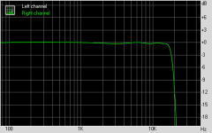
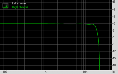
Another test. This time I'm driving an Antek AT-1008 with the primaries strapped to the outputs of a Sony str-dg500 100w amplifier and a 2000ohm resistor. The source is a emu 1212m and recording with the emu 1212m too.
I've included a baseline of the 1212m by itself. I'm guessing the rolloff is the Akm chip's built in 20k filter. I've bypassed all the output stage capacitors so it should hit 20k pretty flat.
I've tried reversing the polarity of the primarys. Makes no difference. This doesn't look to shabby? I'll have to unmount the AT-0358's and try the same test.
Valid test or was this just a kooky experiment?
P.s. I had to drop the protection circuit for this test. I could only squeeze .5w out the secondaries.
Attachments


Last edited:
Your results look so similar to your test circuit limitations, I am not sure you are testing anything beyond that circuit.Another test. This time I'm driving an Antek AT-1008 with the primaries strapped to the outputs of a Sony str-dg500 100w amplifier and a 2000ohm resistor. The source is a emu 1212m and recording with the emu 1212m too.
I've included a baseline of the 1212m by itself. I'm guessing the rolloff is the Akm chip's built in 20k filter. I've bypassed all the output stage capacitors so it should hit 20k pretty flat.
I've tried reversing the polarity of the primarys. Makes no difference. This doesn't look to shabby? I'll have to unmount the AT-0358's and try the same test.
Valid test or was this just a kooky experiment?
P.s. I had to drop the protection circuit for this test. I could only squeeze .5w out the secondaries.
If I ever have time I will try with my oscilloscope, but sunday at best...
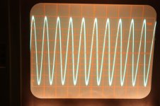
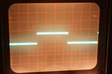
More measurements. This time I'm using an ocilloscope for measurements.
Other test information. The output resistance of the Sony is about 65ohms. For all tests I have a resistor that roughly matches the primary load resistance ratings as appropriate for the transformer. The secondary load is a 8 ohm resistor. Output is 0.5w or less.
The ocillioscope sensitivity is set to 5mv.
I tested the 1212m soundcard and it's output is flat as a board all the way from 20hz to 20k. The sony has a slight drop at higher frequencies so keep that in mind.
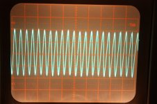
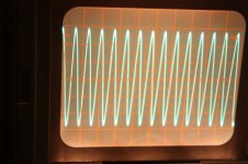
Measurements are at 1k, 7k, 10k, 15k, and 20k.
I barely have a clue about what I'm doing too.
First the at-0358.
Other test information. The output resistance of the Sony is about 65ohms. For all tests I have a resistor that roughly matches the primary load resistance ratings as appropriate for the transformer. The secondary load is a 8 ohm resistor. Output is 0.5w or less.
The ocillioscope sensitivity is set to 5mv.
I tested the 1212m soundcard and it's output is flat as a board all the way from 20hz to 20k. The sony has a slight drop at higher frequencies so keep that in mind.
Measurements are at 1k, 7k, 10k, 15k, and 20k.
I barely have a clue about what I'm doing too.
First the at-0358.
Attachments
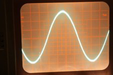
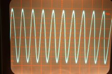
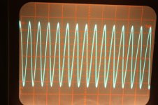
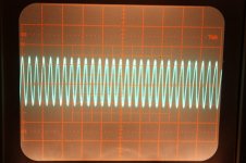
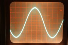
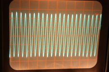
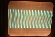
Now the at-1008. Same deal, but I've also included a reference 1k at 0.4v square wave.
Now talk amongst yourselves.")
Now talk amongst yourselves.
Attachments
- Status
- This old topic is closed. If you want to reopen this topic, contact a moderator using the "Report Post" button.
- Home
- Amplifiers
- Tubes / Valves
- Experience with AnTek OPTs?