Ok. Well there it is. Rolloff. I'm not nuts after all.
I made a 20db attenuator for the probe and used an audio power meter that provided an 8 ohm resistor load. That way I could do all the tests for a 1w target.
I did two tests. One with global feedback one without.
Que Terrible!
I made a 20db attenuator for the probe and used an audio power meter that provided an 8 ohm resistor load. That way I could do all the tests for a 1w target.
I did two tests. One with global feedback one without.
Que Terrible!
Attachments

They are wound so you get 400-70-0-330-400 which is useless to me.
I think he must have fixed it since you bought your transformers. I finally found my error (D'oh) and when I turned my first bias supply capacitor around to the correct polarity orientation, it works fine.
Y------G---W Y-----G---W
0 70 400 0 70 400
I grounded the two yellow and everything seems in phase and working as hoped.
Do you have the 4TK400 powering the red board? Sand rectifiers? If so how much B+ are you getting? Tried the 6HJ5's with it?
Yes, yes, 475, and yes.
http://www.diyaudio.com/forums/tube...-new-p-p-power-amp-design-38.html#post2139924
I think he must have fixed it since you bought your transformers. I finally found my error (D'oh) and when I turned my first bias supply capacitor around to the correct polarity orientation, it works fine.
Y------G---W Y-----G---W
0 70 400 0 70 400
I grounded the two yellow and everything seems in phase and working as hoped.
Ah yes. But put your meter cross the two white wires. I just bought mine a month or two ago and the phasing is wrong.

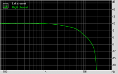
ok. Well there it is. Rolloff.
Wow! Maybe it could be used in a bi-amp setup. Other than that...phooey.
Ok. Well there it is. Rolloff. I'm not nuts after all.
I made a 20db attenuator for the probe and used an audio power meter that provided an 8 ohm resistor load. That way I could do all the tests for a 1w target.
I did two tests. One with global feedback one without.
Que Terrible!
That is wretched!
Bummer, but thanks for publishing the information.I have only ever used low voltage Antec toroids for filament power and power to low voltage analog circuitry. I will steer clear of their opts and most of their high voltage transformers.
Ah yes. But put your meter cross the two white wires. I just bought mine a month or two ago and the phasing is wrong.
I will check it again, because that is what I was afraid might happen, but it seems fine so far, enough to blow up a bad resistor downstream...can't be out of phase and do that very well.
Bummer on the OPTs, I got som and now I feel I have wasted $110 bucks. Sigh, they will get me up and running though...
Looks like 6 dB per octave drop off above 6 KHz. If you do a standard freq. test like I mentioned above (source Z = primary Z), you will likely really be horrified.
This is clearly just a random wound power transformer design, not progressive wound as required for audio.
Thanks to everyone for this information. This sort of confirms what I feared in the first place. AnTek seems OK for power transformers, but if they don't have any history with audio transformers, they might just try winding them the same way...
Thats staggering.
I using plain vanilla Telema power toroids on my main amps. Very simply designed with secondaries straight on top of the primary. I get response up to 50Khz and descent output down to 10hz. I can't understand how Ampilo have got it so wrong. Maybe their trying to interleave and are increasing the interwinding capacitance(which is the main issue I have encountered). I did find that it was important to get things wired up correctly otherwise it would ring out at about 60khz, but other than that no issues. All my designs use Schade feedback to get low enough output impedance to bite on the lower inductance.
Amazing.
Shoog
Can anyone else confirm this independantly? I need more than one data point to feel that it is true. I have a pair and will try to test them sometime, or at least buil them into my amp and see what the response is there, but it will be a while, inamorata in super slo mo new daddy land...
If the windings are connected in phase to an otherwise full wave rectifier circuit, the end result will be half wave rectification at twice the current capability. With enough capacitance at the output of the rectifier, there could still easily be enough voltage to burn things up down stream!
Dave
Dave
I will check it again, because that is what I was afraid might happen, but it seems fine so far, enough to blow up a bad resistor downstream...can't be out of phase and do that very well.
<snip
Sure it can, and I bet you currently have two parallel half wave rectifiers (in phase) - I suspect you will find 0 volts across the two white wires and hence the windings are in phase, not out of phase as they need to be for full wave rectification.
These OPTS might work ok with tubes with low rp.
Sure it can, and I bet you currently have two parallel half wave rectifiers (in phase) - I suspect you will find 0 volts across the two white wires and hence the windings are in phase, not out of phase as they need to be for full wave rectification.
These OPTS might work ok with tubes with low rp.
I see. Keep on learning...
I will check it tonight if I can.
Worst case, I hook it up so the 400V works and the 70v is the problem, then I can use one side of the 70Vs with a half wave rectifier and still get my bias, capping off the other.
Since I only need the 70V for bias and to set a low negative rail for a CCS, the demand shouldn't be too great and I modeled the half wave circuit in PSUD II and it still filters to virtually no ripple (<1mv). It is more important that the B+ work in my plan.
Sigh, only blew up one resistor so far, I think....
To Antek's credit, they will accept returns. I've been very happy with the power transformers that I've gotten from them. That and NJ is next to MD making shipping super fast for me.
I'm debating what to do with my AT-1008's. I was going to use them for a dual channel bass guitar amp. Roll-off may actually be a good thing for my tastes.
I may just have gotten a bad pair. If you have a computer with a sound device, you can probably test them. I just happened to have a 8200 ohm and 910 ohm resistor and a pair of 5.1v zeners to whip together a probe.
For the sake of full disclosure I used the output from an Emu 1212m and input from the motherboard's 24bit Realtek for these measurements. Not super but good enough. Recording on the 1212m is complicated and I can't remember how to do it.
Last edited:
To Antek's credit, they will accept returns. I've been very happy with the power transformers that I've gotten from them. That and NJ is next to MD making shipping super fast for me.
I'm debating what to do with my AT-1008's. I was going to use them for a dual channel bass guitar amp. Roll-off may actually be a good thing for my tastes.
I may just have gotten a bad pair. If you have a computer with a sound device, you can probably test them. I just happened to have a 8200 ohm and 910 ohm resistor and a pair of 5.1v zeners to whip together a probe.
For the sake of full disclosure I used the output from an Emu 1212m and input from the motherboard's 24bit Realtek for these measurements. Not super but good enough. Recording on the 1212m is complicated and I can't remember how to do it.
I will try to measure mine if someone will walk me through it a bit. I could wing it with them built in an amp, but would like to use a consistent technique.
I have a digital oscilloscope with a a function generator and a variety of parts and loads available if someone wants to instruct me. Then I have to find time, but I am on call tonight, so that might be good, if the baby is quiet....
Here's my procedure. First I want to be sure I don't cook my sound card so I put together an attenuator/protection circuit as described in this document http://www.fesb.hr/~mateljan/arta/download/STEPS-user-manual.pdf
I then installed the Rightmark Audio Analyzer software on my computer. Output from the sound card goes to amplifier that has it's own volume control. Output from amplifier goes to some sort of load, probably a hefty 8 ohm resistor. Likewise you connect the speaker output in parallel to your protection circuit and that goes to your soundcard's input.
I started the test with the volume low. Rightmark provides a tool so you can adjust the levels appropriately. I just happened to have an old Rad Shack power meter so I could test consistently at 1w output from the amplifier. Once everything is happy, let it rip.
To measure the frequency response of the Antek OT's, put a resistor in series with the primary, equal to the primary Z, and drive it with a 50 Ohm signal generator. Load the secondary with the specified load Z. Then measure the secondary voltage versus frequency to find the 3 dB (70% V of say the 1 KHz point) voltage frequencies.
Just putting it in an amplifier does not give any real measurement, since a random wound xfmr will have horrible internal capacitance. Driving it with a low impedance stage will make the frequency response still look good, but the hidden penalty is bad distortion from the capacitive loading.
I am a little confused by these two statements. I wish to measure the OPT by itself, outside of my amplifier like you suggest in the first paragraph, but in the second you imply that a low impedance input will not account for the capacitive loading of the trafo.
I think I am just misunderstanding. Can you explain a little more and maybe help me figure out how to use my digital oscilloscope/function generator to measure the OPT?
Whitlabrat's technique uses the amplifier and some software for his soundcard. I could try that, but I think the oscilloscope would be better, I just may have to do some math and plotting on my own.
- Status
- This old topic is closed. If you want to reopen this topic, contact a moderator using the "Report Post" button.
- Home
- Amplifiers
- Tubes / Valves
- Experience with AnTek OPTs?