I would guess that in the first set of measurements, pin 5 measured 0.24V instead of 24V, it is easy to misread a DMM, the numbers look the same. The grid (pin 5) would likely be very close to ground in a self-bias amp. That gives a bias voltage of 33V for the 6P3S and 28V for the 6P3S-E. Ahhh, possibly gassy tube, is that what you mean Anatoly? 24V on the grid?
I attached a schem, which shows two possible variations for the output section of your amp (for one channel). The upper one shows individual cathode resistors and cap for each output tube (R3 and C2). The lower one shows a shared cathode resistor and bias cap (R3 and C2). Perhaps you can trace the circuit and see which variation you have, and fill in the values of R1 to R4 and C1 and C2. That will give you the output schematic of your amp, which is a good start. If the value of R3 is known, it is easy to calculate the power dissipation of the tube at quiescent conditions (idle). One quick check to see if you have the upper or lower schematic is to check the resistance between pin 8 of each tube in the same channel, if it is around 1 ohm or so, then the lower schematic would correspond to your amp.
If you can measure the cathode resistor/s (R3), you can calculate the power dissipation of the output tubes very easily. For example, if your amp is like the upper schematic, and R3 is 470 ohms, and your 6P3S-E measure 28.4V at pin 8 (cathode), then V = IR, 28.4 = I x 470, I = 0.060 amps = 60mA. The power dissipated by the output tube would be voltage across the tube x current through the tube = (390 - 28.4) x 0.060 amps = 21.7 watts.
Attachments
Last edited:
I would guess that in the first set of measurements, pin 5 measured 0.24V instead of 24V, it is easy to misread a DMM, the numbers look the same. The grid (pin 5) would likely be very close to ground in a self-bias amp. That gives a bias voltage of 33V for the 6P3S and 28V for the 6P3S-E. Ahhh, possibly gassy tube, is that what you mean Anatoly? 24V on the grid?
I attached a schem, which shows two possible variations for the output section of your amp (for one channel). The upper one shows individual cathode resistors and cap for each output tube (R3 and C2). The lower one shows a shared cathode resistor and bias cap (R3 and C2). Perhaps you can trace the circuit and see which variation you have, and fill in the values of R1 to R4 and C1 and C2. That will give you the output schematic of your amp, which is a good start. If the value of R3 is known, it is easy to calculate the power dissipation of the tube at quiescent conditions (idle). One quick check to see if you have the upper or lower schematic is to check the resistance between pin 8 of each tube in the same channel, if it is around 1 ohm or so, then the lower schematic would correspond to your amp.
If you can measure the cathode resistor/s (R3), you can calculate the power dissipation of the output tubes very easily. For example, if your amp is like the upper schematic, and R3 is 470 ohms, and your 6P3S-E measure 28.4V at pin 8 (cathode), then V = IR, 28.4 = I x 470, I = 0.060 amps = 60mA. The power dissipated by the output tube would be voltage across the tube x current through the tube = (390 - 28.4) x 0.060 amps = 21.7 watts.
I'm pretty sure it read 24v, but I could have misread it, but pretty certain I didn't.
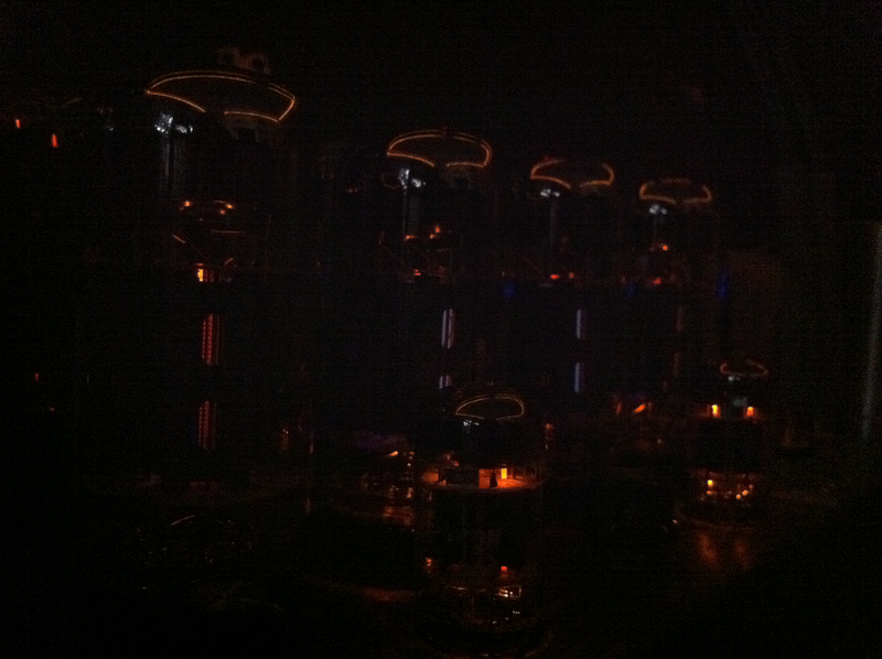
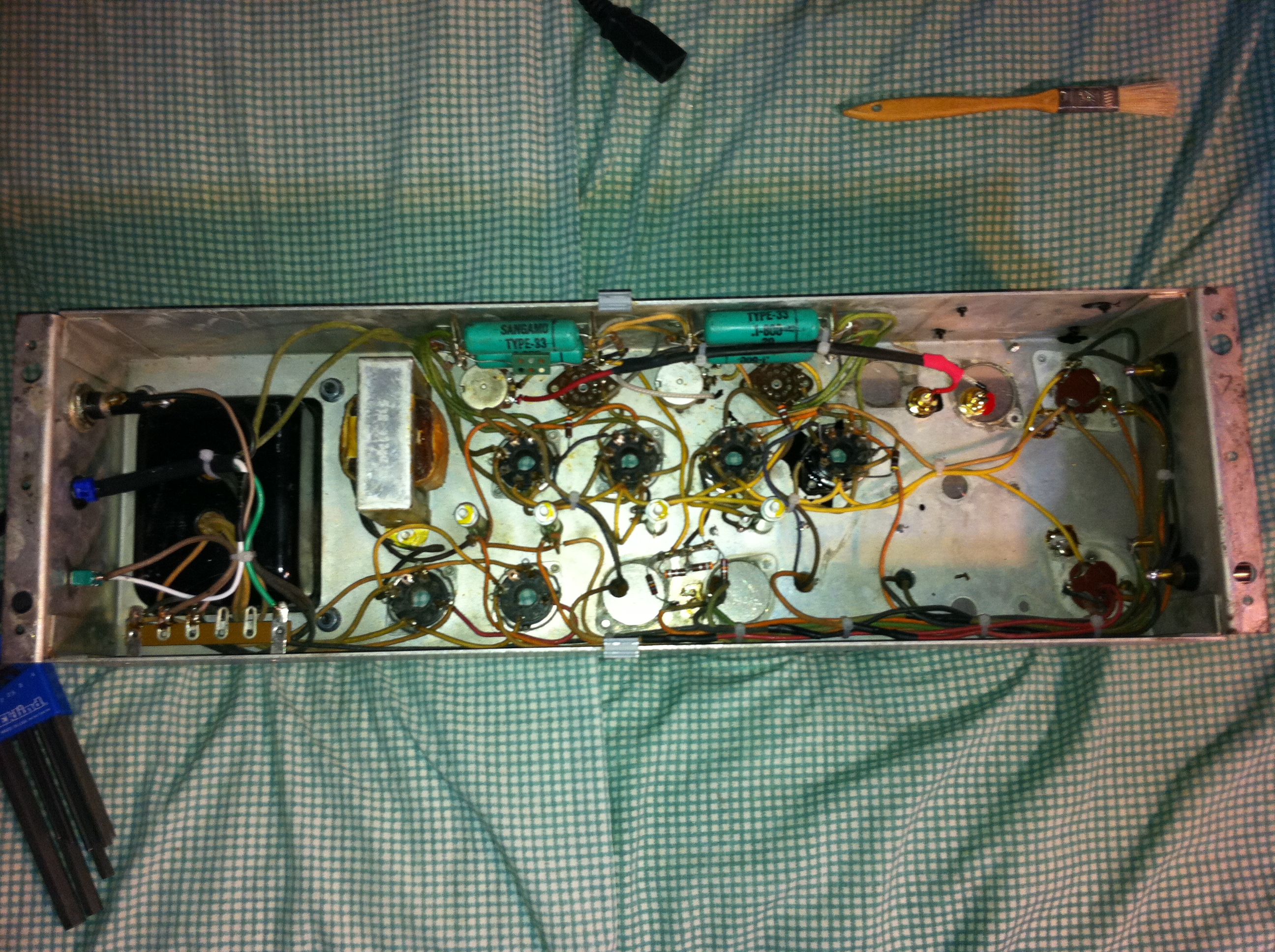
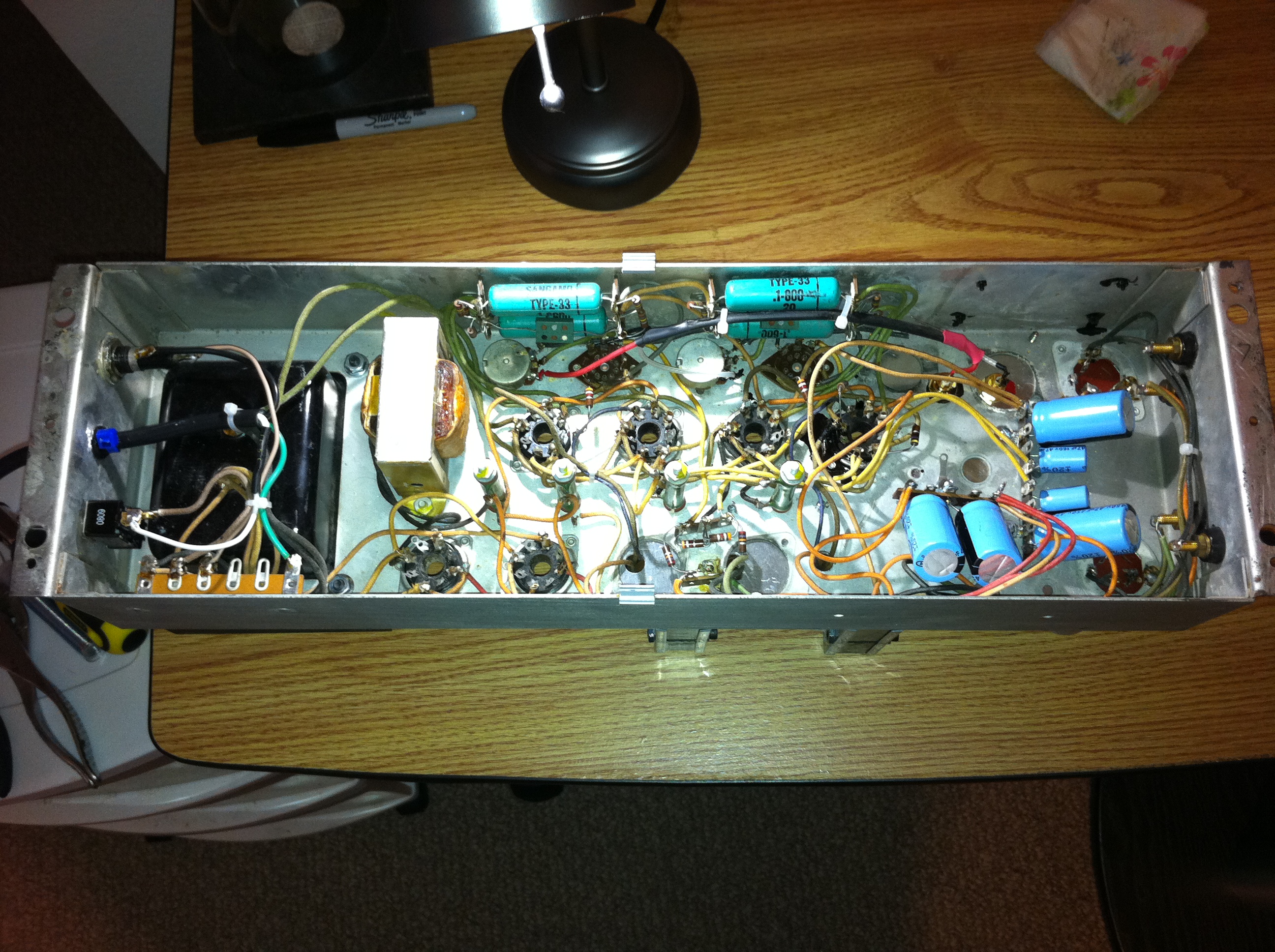
Anyway, here's the full rez images of inside the amp. I'm not home now so can't take better pics, but will when I get some time with my big camera. Maybe by looking at these you can tell which design it is. And I do appreciate all the help you guys are offering me.
Also, don't some of those voltages seem a bit odd, especially the B+ at nearly 400v?!
Also, don't some of those voltages seem a bit odd, especially the B+ at nearly 400v?!
388V and 399V are only about 3% different. Individual component tolerances were up to 20% (those carbon comp. resistors for example) as a default back in the in the 50's-60's, so you can expect quite a bit of variation throughout the amp.
In fact, that's one area that is easy to tweak these days, given the much higher tolerance of new components. After the schematic is determined and each component's marked value is noted, you can assess whether your sub-circuits are satisfactorily up to spec by comparing the marked values with the measured (or calculated) performance values, and upgrade parts as necessary.
One possibly easier way to trace the circuit is to just draw a sketch of the amp guts and draw in the wires exactly as you see them. I can turn that into a schematic fairly easy. But I don't want to try to trace it using the photographs. It would be so much easier to do in person.
..Todd
The 3% difference isn't what concerns me, it's the high voltage. Is running at nearly 400 volts B+ a good thing? I can't help but imagine that it should be quite a bit lower. That's running right near the max of the 6L6 family!
When I get the time, I can open the amp back up and trace out the circuit. I'm sure I can handle that.
Individual cathode bias resistors, 270K from control grids to ground;
if you indeed had +28 on first grid the tube was gassy and run away.
Have you noticed red anode? If not, it was misreading of the voltage.
270K?! Shouldn't that be more like 200-300 ohms? And if you remember, the seam of the plates WERE glowing red.
No, it should not be like 200-300 Ohm, it should be 1000 times more. However, as soon as some your tubes are gassy you may try to solder in parallel with that resistors some 100 kiloohm additionally.
Then I'm getting some conflicting information between here on the forum and elsewhere. How and why would my tubes "get" gassy? And why do I get the feeling you are annoyed with me?
Then I'm getting some conflicting information between here on the forum and elsewhere. How and why would my tubes "get" gassy? And why do I get the feeling you are annoyed with me?
It is common with NOS tubes to be gassy. They are not perfect, and get gassy over time. However, they have some getter flash remained on the glass (that silver mirror in them) that absorbs gases, but sometimes it is not enough.
Ionized gases cause screen grid currents that decrease negative bias of control grid in respect to cathode. That causes higher currents, more heat, and as the result even higher grid current, and so on... It is called run away.
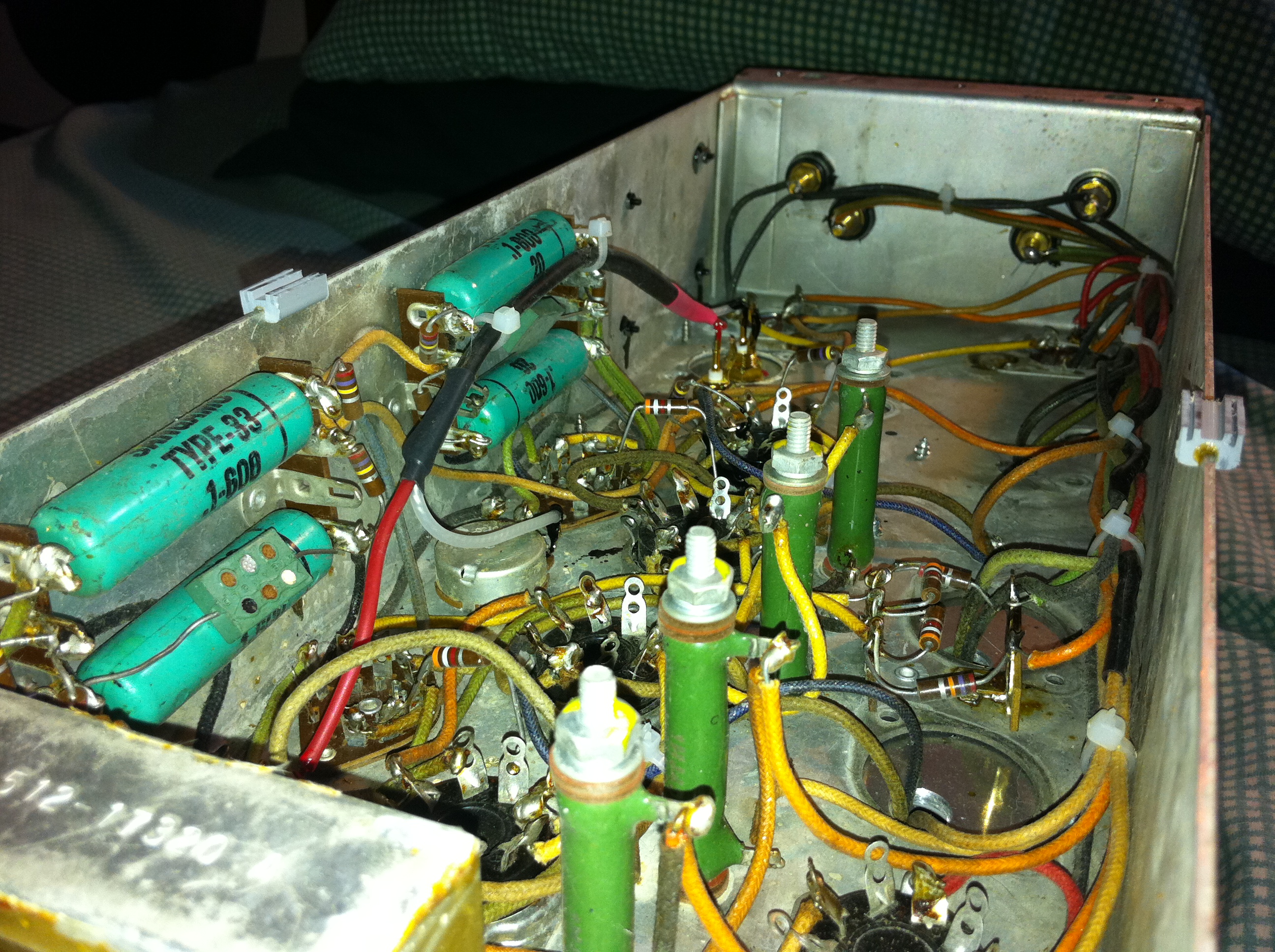
Speaking of 270 kiloohm, you can see it on your picture. Resistors from control grids to ground have strips: red, violet, yellow. That means 2, 7, 4. I.e. 27*10^4 Ohm.
Speaking of 270 kiloohm, you can see it on your picture. Resistors from control grids to ground have strips: red, violet, yellow. That means 2, 7, 4. I.e. 27*10^4 Ohm.
I was under the assumption that the control grid resistors were those large green ones bolted to the chassis. The only two 270K ohm resistors I see are on those small solder strips next to the rectifier sockets. They also have a couple of 3.9K ohm resistors with them, but it looks like they go to the driver sockets.
Sorry for my ignorance when it comes to this stuff. Heck, I'm using a resistor application on my iPhone to help me out with the values!
This a bump to keep my Place as I have some insite I have done fender and marshall amp repair and when you can see the pretty violet glow they are biased alittle high sound great but tubes dont last along time. I will post later my observations as a musician and repairman...
Elwood
PS Groove tube has a bunch of info on different tubes and optimum bias amperage...
Hint pin 8 place a 1 ohm resistor on pin 8 measure voltage drop across resistor mv translates to ma
Elwood
PS Groove tube has a bunch of info on different tubes and optimum bias amperage...
Hint pin 8 place a 1 ohm resistor on pin 8 measure voltage drop across resistor mv translates to ma
Last edited:
I also tried taking some measurements with the amp off and unplugged of course, from Pin #8 of the output sockets. The left channel measures 244K ohms and the right 199K ohms. Does that seem correct to you?
You probably measure wrong pins. Pin 8 is cathode, where that big green resistors are soldered to. They should be in hundred of ohm range.
The 3% difference isn't what concerns me, it's the high voltage. Is running at nearly 400 volts B+ a good thing? I can't help but imagine that it should be quite a bit lower. That's running right near the max of the 6L6 family!
The 6L6 has a max plate voltage of 500V. Not sure how those Russian tubes are rated though, but I doubt 400V is a concern. I saw a Ken-Rad datasheet that lists a bunch of suggested 400V operating points. And that was for the very early (1930's model?) 6L6.
Take Waveborne's advice. He knows tube amps!
..todd
You probably measure wrong pins. Pin 8 is cathode, where that big green resistors are soldered to. They should be in hundred of ohm range.
No, I didn't "probably" measure the wrong pins. I measured the cathode resistors for a reason, to find out the size of them. And yes, they are in the hundreds, 244 and 199 ohms. I just made a typo last night from being tired and all that talk about Kohms, not to mention I got mixed up with cathode bias resistors and control grid resistors.
It looks to me like there is a shared cathode resistor for each output pair of tubes, like in the lower of the 2 schematics in post 63. The 2 green power resistors close to the rectifiers could be part of CLC power supply filters, and the other 2 green power resistors are the cathode reistors for the output tubes.
Those 2 green cathode resistors should be the same value, and there should be a capacitor wired in parallel to each resistor. Are those caps old ones? Also it can be difficult to measure a resistor when a cap is in parallel, usually the DMM will wander and then settle on a final value.
It does seem the amp is definitely biased on the hot side, even with 33V on the grid and a 244 ohm common cathode resistor, you have around 24W dissipation, the info I have for 6P3S is 20.5W for the plate and 2.75W for the screen.
It looks to me like there is a shared cathode resistor for each output pair of tubes, like in the lower of the 2 schematics in post 63. The 2 green power resistors close to the rectifiers could be part of CLC power supply filters, and the other 2 green power resistors are the cathode reistors for the output tubes.
Those 2 green cathode resistors should be the same value, and there should be a capacitor wired in parallel to each resistor. Are those caps old ones? Also it can be difficult to measure a resistor when a cap is in parallel, usually the DMM will wander and then settle on a final value.
It does seem the amp is definitely biased on the hot side, even with 33V on the grid and a 244 ohm common cathode resistor, you have around 24W dissipation, the info I have for 6P3S is 20.5W for the plate and 2.75W for the screen.
Being that the value for each pair of output tubes is identical, I also assumed that each pair shares a single resistor. I believe the caps for those resistors are the two brand new 47uF - 160v caps that I installed as they replace part of the old original three section can caps that died. And the DMM did take a few seconds to settle down on a final value.
Probably a dumb question, but what is "CLC"?
- Status
- This old topic is closed. If you want to reopen this topic, contact a moderator using the "Report Post" button.
- Home
- Amplifiers
- Tubes / Valves
- Excellent NOS Russian 6Pi3C/6N3C (6L6GC) Tubes...