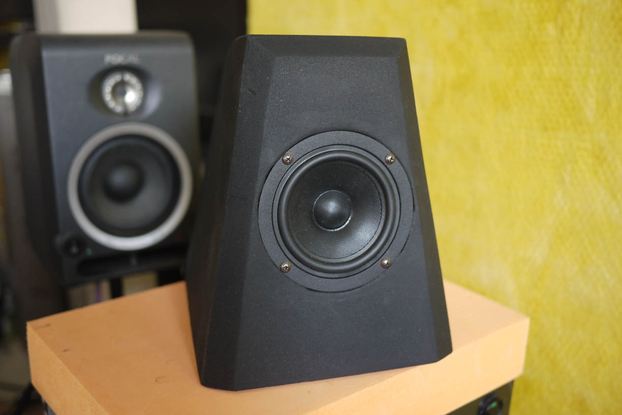
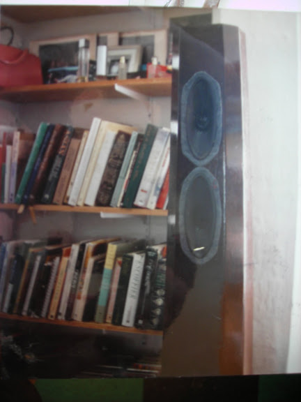
I finished the black painted faceted sealed box for my 10f/8424.They are looking really good and I am very happy with them!
The faceted baffle fixed a baffle-step problem with the original, and it seems to give a very smooth response. With this geometry box (1.6L no parallel walls, truncated pyramid with rounded top) and faceted baffle, I get an excellent one-driver speaker that approaches the LS3/5a small monitors. This was my target : one-driver small monitor, sealed box, LT, 80-20khz response, clean low distortion.
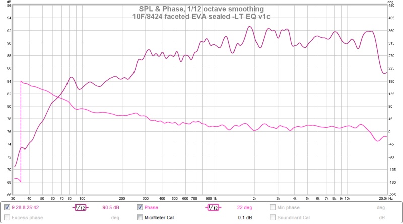
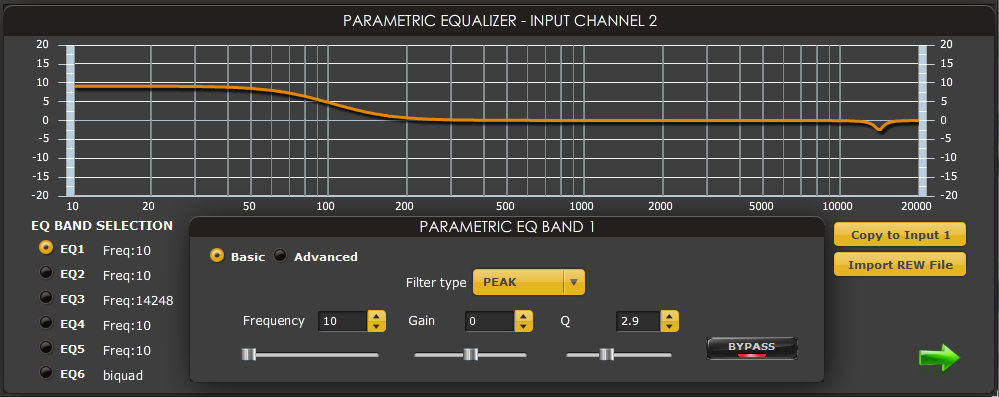
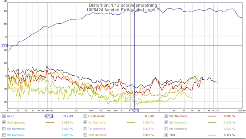
For this I apply a linkwitz transform to lift the bass and a single EQ peak at 14300hz to tame the high end a little. But this second EQ is right on the edge of my hearing range so maybe not critical, but it does seem to help and makes it easier to listen to the speaker for longer sessions. The 10f/8424 has such low distortion and excellent driver control that it responds very well to LT without causing distortion problems.
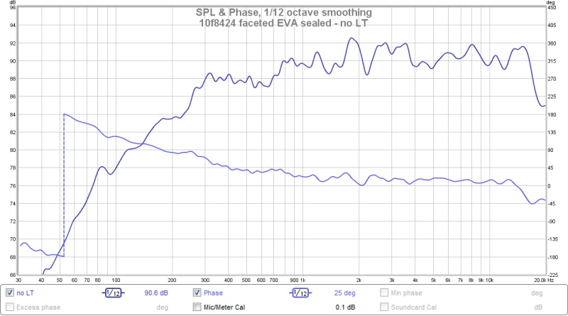
Measurements are at 20cm and calibrated response shown in graphs is accurate. very very happy.
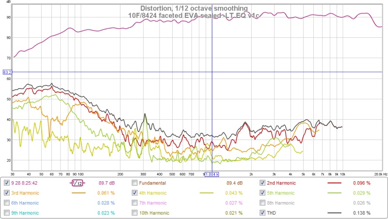
and without the linkwitz transform to show the low distortion. I may play with the LT in the future to see if I can get a better balance of extension to 80hz and low distortion.
I do not concur with xrk971 on results achieved with this enclosure. Relative to X's implementations with 10f, and in comparison with your SB65 in tapered transmission line, the ripple magnitude above 1kHz is about twice as great.
Given external baffle's similarities to X's, this leaves enclosure as source of defect.
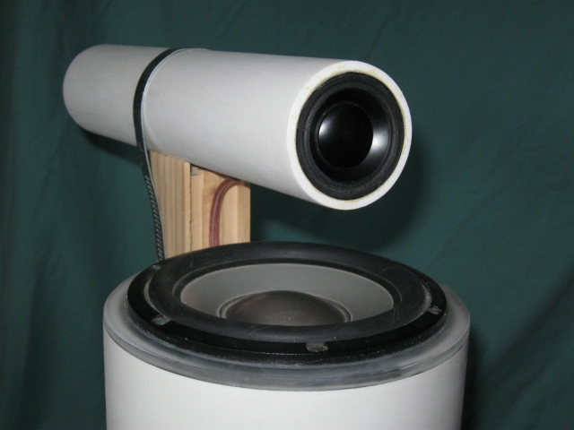
My results with 10f mounted in end of 115mm diameter pipe (4" ID PVC) measured at 50cm:

The polar data gives good indication of how EQ of on axis response will translate to off axis performance. Large window was used, thus ripple below 1kHz is somewhat exaggerated. Baffle step is easy to fix. So even here with worst possible baffle choice of circle, the 10f performance is much smoother than in your implementation.
I do not concur with xrk971 on results achieved with this enclosure. Relative to X's implementations with 10f, and in comparison with your SB65 in tapered transmission line, the ripple magnitude above 1kHz is about twice as great.
Given external baffle's similarities to X's, this leaves enclosure as source of defect.
My results with 10f mounted in end of 115mm diameter pipe (4" ID PVC) measured at 50cm:
View attachment 506545
The polar data gives good indication of how EQ of on axis response will translate to off axis performance. Large window was used, thus ripple below 1kHz is somewhat exaggerated. Baffle step is easy to fix. So even here with worst possible baffle choice of circle, the 10f performance is much smoother than in your implementation.
Well at least compared to my SB65 tapered transmission line, the measurement distance is very different. The SB65 was measured at 5cm while this 10f/8424 was measured at 20cm. I live in a small apartment so my measurements are in small room with many things (bookcases, piano keyboard, table, sofa, TV, computer...). This increase in distance introduces many more room artifacts into my measurements.
I honestly don't see that much difference between my ripple and your ripple above 1khz. Mine is centered around 90.5db and goes up to about 92.2db and down to about 89.5db except for one dip at 1.5khz which goes down to about 88.5. So this is about +/- 1.4db (if we skip the 1.5khz dip) or +/-1.8db if we do include it. Looking at your graph it appears to also be in the +/-2db range. I can't find the specific data plot you are referring to. I also don't know exactly what type of smoothing you or X are using in your plots.

I guess we are both measuring in normal rooms (not anechoic chambers) so I guess there must be at least 1db noise error between measurements/people/rooms.... Even when I repeat measurements I rarely can get them perfectly the same.
Also compared to X's measurements, he is measuring in a dedicated large clean room which might introduce less FR artifacts. And I think his measurements are also in the low +/-2db range.
I personally think that getting a measurement in my room, at 20cm distance with only a 1/12db smoothing and getting close to +/-1.5db is a great result for this driver,baffle,enclosure,material choice. If I was +/-4db and you or X were +/-2db then I would be convinced this is above the noise of different measurement setups. This is the difficulty of each of us measuring in our own rooms, with different equipment, different amps, different microphones and trying to make statements about our designs.
Later I can take some measurements of the SB65 taper transmission line at 20cm distance so we can compare more directly. It is very difficult for me to get clean measurements at 0.5m distance due to the nature of my room and the artifacts that it introduces.
I also think back to this early diffraction work of Dr. Harry Olsen 1950 experiments at RCA research labs in Princeton University, which I think are still considered valid.
Diffraction Information & Graphs


And that putting a speaker at the end of a cylinder (c) produces large ripples, while spheres (a) and truncated pyramids (J and L) produce some of the least ripples.
Diffraction Information & Graphs
And that putting a speaker at the end of a cylinder (c) produces large ripples, while spheres (a) and truncated pyramids (J and L) produce some of the least ripples.
Actually you don't want to use a hot wire (electric carving knife) with EVA, it does not work. That only works with styrofoam. EVA is heat resistant so the hot wire just slowly burns the EVA and makes a mess.
Here is a video on cutting EVA foam
https://www.youtube.com/watch?v=q1h7J9JZQWs
But yes EVA does respond to heatguns to soften the material and shape it. It can be easily molded into bowls and curves. Here is a video about forming EVA foam
https://www.youtube.com/watch?v=hNLKvlYcgmM
you can see from these videos that they mostly use those 10-12mm thick floor tiles (smooth on one side, bumps on the other side)
Thanks for the links.
") That really helps visualize working with the stuff. It appears that an Xacto or similar razor knife is the way to go. In that way it is a little like floppy foamcore.
That really helps visualize working with the stuff. It appears that an Xacto or similar razor knife is the way to go. In that way it is a little like floppy foamcore.Speaking of trapezoids, diffraction and foam, a smaller version of this old design should be an interesting candidate for a fast build in EVA or foamcore. It was actually pretty huge, and yet was built with 1/4" plywood. The faceted construction both reduces diffraction and makes for a very strong construction with short spans. That's why I think it might be amenable to lightweight foam.
Essentially, the construction method is like a boat or a balsa model airplane. Glue the side panels to formers, and then caulk up the seams. If using foam core, hot melt glue would be easy.
Making it bipolar would reduce the issue of newton's 3rd law. The drivers would oppose each other instead of the cabinet.
For simulation purposes, it's an ML-TQWT with conical expansion.
I don't mean to hijack your thread, btw. Just throwing out an idea.
Essentially, the construction method is like a boat or a balsa model airplane. Glue the side panels to formers, and then caulk up the seams. If using foam core, hot melt glue would be easy.
Making it bipolar would reduce the issue of newton's 3rd law.
The drivers would oppose each other instead of the cabinet. For simulation purposes, it's an ML-TQWT with conical expansion.
I don't mean to hijack your thread, btw. Just throwing out an idea.
jeshi,
You showed interest fibre glass cones from Discovery series.
Yesterday received backorder 22W/8534 original ordered with 18W/8434, attach out of box TS specs and impedance plots for my pairs of 10F/18W/22W.
You showed interest fibre glass cones from Discovery series.
Yesterday received backorder 22W/8534 original ordered with 18W/8434, attach out of box TS specs and impedance plots for my pairs of 10F/18W/22W.
Attachments


Last edited:
Well at least compared to my SB65 tapered transmission line, the measurement distance is very different. The SB65 was measured at 5cm while this 10f/8424 was measured at 20cm. I live in a small apartment so my measurements are in small room with many things (bookcases, piano keyboard, table, sofa, TV, computer...). This increase in distance introduces many more room artifacts into my measurements.
I honestly don't see that much difference between my ripple and your ripple above 1khz. Mine is centered around 90.5db and goes up to about 92.2db and down to about 89.5db except for one dip at 1.5khz which goes down to about 88.5. So this is about +/- 1.4db (if we skip the 1.5khz dip) or +/-1.8db if we do include it. Looking at your graph it appears to also be in the +/-2db range. I can't find the specific data plot you are referring to. I also don't know exactly what type of smoothing you or X are using in your plots.
I guess we are both measuring in normal rooms (not anechoic chambers) so I guess there must be at least 1db noise error between measurements/people/rooms.... Even when I repeat measurements I rarely can get them perfectly the same.
Also compared to X's measurements, he is measuring in a dedicated large clean room which might introduce less FR artifacts. And I think his measurements are also in the low +/-2db range.
I personally think that getting a measurement in my room, at 20cm distance with only a 1/12db smoothing and getting close to +/-1.5db is a great result for this driver,baffle,enclosure,material choice. If I was +/-4db and you or X were +/-2db then I would be convinced this is above the noise of different measurement setups. This is the difficulty of each of us measuring in our own rooms, with different equipment, different amps, different microphones and trying to make statements about our designs.
Later I can take some measurements of the SB65 taper transmission line at 20cm distance so we can compare more directly. It is very difficult for me to get clean measurements at 0.5m distance due to the nature of my room and the artifacts that it introduces.
It isn't the wide dips related to baffle diffraction, more specifically the peak at about 1.8kHz, and the broad peaks at about 2.5kHz and 3.5kHz in your plots that seem out of place. 20cm measurement is very close relative to driver diameter and baffle width. Even so, if speaker is about 1m above floor, and well away from walls, measurement at 20cm should be smoother in 1kHz-4kHz range. With close measurement direct to reflected ratio is high, and use of shorter windows of 3-6ms with no smoothing should provide good details.
Here are overlays of measurements at 20cm and 50cm of pipe mounted 10f with 6ms Blackman-Harris 4 term windows:

The little ripples all occur within the first major ripple due to baffle that is just above where baffle step compensation filter would be applied with normal EQ techniques. The major baffle ripple is then readily equalized with single low Q filter to bring response in line with rest of higher frequencies.
The change in peak locations of fine ripples is caused primarily by cone geometry, not the speaker baffle. Typically best measurements are done at greater than eight times the driver's diameter. At such distances, path length difference to all points on driver surface become negligible; propagating wave front becomes about as uniform as it will get.
Linkwitz has nice page on diffraction effects. Driver centered in circular baffle 2-4 times driver diameter is worst in terms of baffle induced ripple.
My sense is that your little EVA enclosure, though of appropriate volume, does not maximize back wave control to degree that my pipe does, or X's tapered arrangements do. Back waves make equalization more difficult, and even when this is done, I sense that imaging detail is lost.
jeshi,
You showed interest fibre glass cones from Discovery series.
Yesterday received backorder 22W/8534 original ordered with 18W/8434, attach out of box TS specs and impedance plots for my pairs of 10F/18W/22W.
awesome! Throw a tweeter on that and you will have a vandersteen Quattro
Looking forward to hear your impressions and FR/distortion measurements of the 18W and especially the 22W (I will look out for your thread on these).
I am starting to look around at some 8" (sub)woofers and my short list right now is : 830667, 22W/8534, SB23NRXS, RSS210HF, (maybe DCS205). Zaph had really good measurements of the SB23NRXS and RSS210HF and gainphile loves the bigger RSS265HF. The 830667 and 22w/8534 are probably the ones that will fight it out in the end for me unless my SBacoustics fan-girl-ism wins over and I go for the SB23RNXS.
Last edited:
jeshi,
You showed interest fibre glass cones from Discovery series.
Yesterday received backorder 22W/8534 original ordered with 18W/8434, attach out of box TS specs and impedance plots for my pairs of 10F/18W/22W.
Nice set of drivers there Byrtt. Can't wait to see what you will build. Will it be a FAST or will you add a tweeter for 3 way?
Nice set of drivers there Byrtt. Can't wait to see what you will build. Will it be a FAST or will you add a tweeter for 3 way?
Year they quite nice hardware and think the picture with three different sized cones inspire to think multiway : ) jeshi pointed to nice vanderstern Quattro and one could quick get Dunlavy config on mind something ala W22/W18/10F/W18/W22. But think multiway is too many complicated compromises and the day i enter that road will probably choose complicated synergy route ala build by bwaslo.
Will keep it 2 way FAST and have now three woofers 18W/22W/SPH-250KE i can pair 10F and make trials. A combination of input from Jeff Bagby spreadsheet "Diffraction & Boundery Simulator 1.2" and Overkill Audio talk about wall mounted speakers have me found a trail i like to try. Its because if box is 8" or less deep mounted on wall that spreadsheet shows at a particular point on wall in my room i can get even 18W with sealed 82Hz f3 to play down to 20-30Hz with room gain, and 22W with sealed 52Hz f3 have more power. 10F will be at 5 feet height and woofer above 10F but doesn't matter if i can angle front baffle few degrees. Should this not work in reality think will look at the Linkwitz inspired 2 way builds Barleywater share, but my room here in cellar is so small i rather like them on wall if it sound reasonable.
Below picture 1 is dirty quick baffle example from the spreadsheet with 10F and 18W at a particular spot on wall that shows "combined baffle diffraction and room augmentation summation". Then at picture 2 imported from frd-file to REW and hit EQ icon at first plot see the room gain, next plot i set a HP 82Hz to sim sealed 18W and in third plot just some dirty quick fun setting few EQ's. Third picture is 22W but based on 18W box size so will need some more work to be real true model. Don't know if it will work real world but is curious to find out if one will get that deep bass from so simple two way FAST and how it sound.
Attachments


Last edited:
Byrtt,
Thanks for sharing the wall FAST approach with boundary and diffraction simulator - I will have to look into that program. Looks like a nice result of you can hit 25Hz. I am building a test MLTL flat wall speaker using the A7.3 right now. I will see how that turns out but looks like the boundary simulator can tell me the room gain I can expect. My box is tuned to about 50Hz with a gentle toll off.
Thanks for sharing the wall FAST approach with boundary and diffraction simulator - I will have to look into that program. Looks like a nice result of you can hit 25Hz. I am building a test MLTL flat wall speaker using the A7.3 right now. I will see how that turns out but looks like the boundary simulator can tell me the room gain I can expect. My box is tuned to about 50Hz with a gentle toll off.
It isn't the wide dips related to baffle diffraction, more specifically the peak at about 1.8kHz, and the broad peaks at about 2.5kHz and 3.5kHz in your plots that seem out of place. 20cm measurement is very close relative to driver diameter and baffle width. Even so, if speaker is about 1m above floor, and well away from walls, measurement at 20cm should be smoother in 1kHz-4kHz range. With close measurement direct to reflected ratio is high, and use of shorter windows of 3-6ms with no smoothing should provide good details.
Here are overlays of measurements at 20cm and 50cm of pipe mounted 10f with 6ms Blackman-Harris 4 term windows:
View attachment 506668
The little ripples all occur within the first major ripple due to baffle that is just above where baffle step compensation filter would be applied with normal EQ techniques. The major baffle ripple is then readily equalized with single low Q filter to bring response in line with rest of higher frequencies.
The change in peak locations of fine ripples is caused primarily by cone geometry, not the speaker baffle. Typically best measurements are done at greater than eight times the driver's diameter. At such distances, path length difference to all points on driver surface become negligible; propagating wave front becomes about as uniform as it will get.
Linkwitz has nice page on diffraction effects. Driver centered in circular baffle 2-4 times driver diameter is worst in terms of baffle induced ripple.
My sense is that your little EVA enclosure, though of appropriate volume, does not maximize back wave control to degree that my pipe does, or X's tapered arrangements do. Back waves make equalization more difficult, and even when this is done, I sense that imaging detail is lost.
Barleywater, you make some very good discussion points, but really my room is not that clean to be be able to say anything about +/-1db artifacts. Also I did not measure at 1m above floor and in the middle of the room and far from walls (or other items). This is just not really possible given my small Japanese apartment and how much stuff I have in it. My previous measurements were at the location where I use the speaker(and where you see in the photo): on top of my piano keyboard, near my computer, basically my home studio. It was about 0.2m to the left of that fiberglass panel, and 0.15m above the keyboard with those other items very close by.
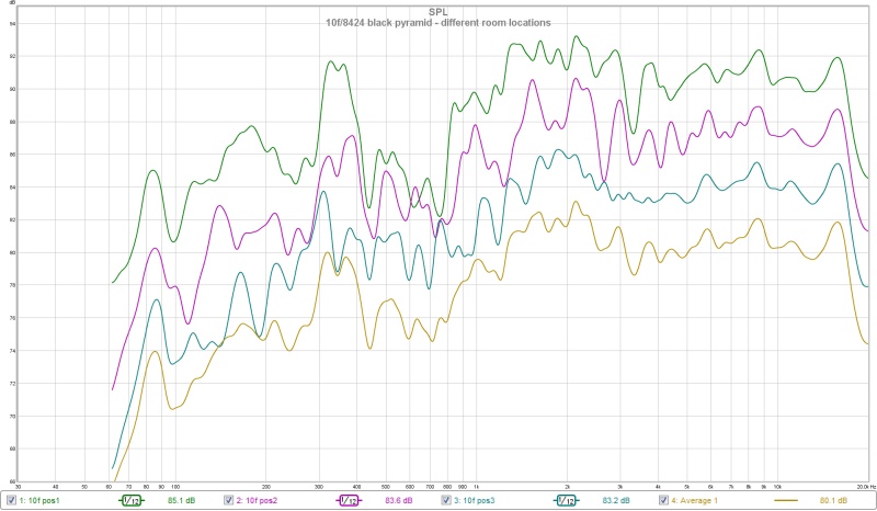
Here are some new measurements of this black faceted pyramid 10f/8424. I measure at 0.5m at three different locations around my room. Smoothing is 1/12db octave (I use REW). SPL levels are calibrated and this is really the max volume this 10f/8424 wants to play fullrange with the LT I applied. But this is not my application volume, I usually play the speaker about 4-6db softer than this even though I sit about 0.8-1m from the speaker.
The responses of the different room locations are close, but each location can introduce some 1-4db artifacts into the curve. I also averaged the 3 locations.
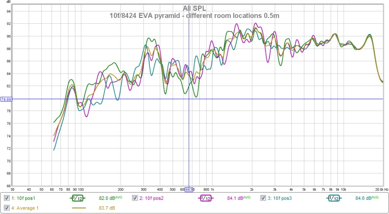
But yes you might be right that this trapezoid shape is maybe causing a 2db broad bump at 2khz (pos3 measurement). But this is exactly as predicted from the baffle step simulation. So I don't think this has anything to do with EVA or backwaves or stuffing or the enclosure. I think all the artifacts in the plots can be explained by bafflestep diffraction and room artifacts.
I am starting to look into how to battery power my TPA3116/miniDSP box so that I could eventually take it and my speakers out into a field/park to do open-air measurements. But until then, maybe the above pos3 in my room might give the cleanest location for measurements from now on.
Attachments


Last edited:
That matches your baffle prediction well. It seems you have about 5dB of baffle step loss that you should apply to flatten the response. Maybe -5dB Q=0.5 at 900Hz?
yes I agree and I actually did try a baffle step correction around the 900hz point before. It made it much flatter, but when listening it did something to the sound that didn't sound right. Maybe it caused a phasing or time artifact which messed up the imaging. It just seemed to "defocus" the image a little. But this was using my focal cms40 as the left speaker (2way design). But I just felt it sounded better without that extra EQ, bafflestep correction at 900hz.
Once I get a pair of 10f/8424 faceted pyramids built, then I really can judge imaging properly and try the bafflestep correction around 900hz again.
But I have to admit, looking at barleywaters plots, linkwitz's page, and linkwitz's lxmini, I am curious now about trying the 10f/8424 in a no-baffle tube (either PVC or an EVA roll). Just using the round frame of the 10f as the "baffle", no additional shape. Either like the linkwitz lxmini (semi-open-baffle), or in a transmission line tube.
Last edited:
Here is the pos3 measurement with phase (not the other room locations).
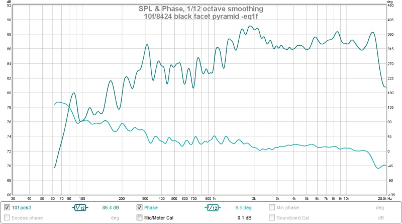
One thing I really like about this particular EQ is the very linear fall off from 2000hz down to 75hz. Maybe 3db per octave? Even though it is not flat, it is flat (linear fall) It is very easy for the ear/brain to adjust to gentle linear rise/falls but not to steps/dips. So for working with music, actually having a linear response from 75hz to 2000hz is great, even though that linearity is slightly tilted. There is no point where I have to think (oh this is that point at 100hz where it switched from flat to a 6db/oct drop). I just have to think that above 2khz it flattens out.
One thing I really like about this particular EQ is the very linear fall off from 2000hz down to 75hz. Maybe 3db per octave? Even though it is not flat, it is flat (linear fall)
It is very easy for the ear/brain to adjust to gentle linear rise/falls but not to steps/dips. So for working with music, actually having a linear response from 75hz to 2000hz is great, even though that linearity is slightly tilted. There is no point where I have to think (oh this is that point at 100hz where it switched from flat to a 6db/oct drop). I just have to think that above 2khz it flattens out.Attachments

Last edited:
Are you running latest REW that has frequency dependent windowing? You should try this with 4-7 cycle windowing.
Position 3 and plot overlays give better sense of what you've got.
SB65 cannoli will give sharpest imaging.
The roll off below 2kHz will not hold up with extended listening.
I've started some baffle experiments with 4" pipe mount. Router circle jig is dialed in for cutting holes that fit pipe. First baffle is about 12" diameter circle with offset. Survey with this has given me idea for a comparison set of measurements which I will be able to run; hopefully will have provocative results for further pondering and discussion.
Linkwitz's site is great.
Preliminary naked 10f experiments aren't inspiring for its use in LXmini. Motor is noisiest compared to FU10RB and TC9FD. Vifa NE180 blows all three away in this department, as doubtless the Satori will too.
Are you running latest REW that has frequency dependent windowing? You should try this with 4-7 cycle windowing.
Position 3 and plot overlays give better sense of what you've got.
SB65 cannoli will give sharpest imaging.
The roll off below 2kHz will not hold up with extended listening.
I've started some baffle experiments with 4" pipe mount. Router circle jig is dialed in for cutting holes that fit pipe. First baffle is about 12" diameter circle with offset. Survey with this has given me idea for a comparison set of measurements which I will be able to run; hopefully will have provocative results for further pondering and discussion.
Linkwitz's site is great.
Preliminary naked 10f experiments aren't inspiring for its use in LXmini. Motor is noisiest compared to FU10RB and TC9FD. Vifa NE180 blows all three away in this department, as doubtless the Satori will too.
Looking forward to see your baffle experiments. I also think there is a lot more to explore in baffle shapes and diffraction effects. I actually wonder if baffle shape and diffraction should not be the first design decision after driver selection and before box type and size. I know I started my designs with baffle diffraction sims.
I also agree about the Satori (and cousin NE180) blowing away these fullrange drivers. I like the no crossover aspect of fullrange and the 10f/8424 does sound really quite good, but they just don't sound as good as my RS28f/satori. that is why I want to just use the 10f as a very specific (one driver, no crossover) midrange focused mixing/composing tool. And I was actually disappointed in my first attempt at a SB65/satori 2way. Rs28f is better in the treble (1.5khz and up) than the sb65 and the Satori is better in the midrange and bass (under 1.5khz) than the SB65. Once I improve the integration and crossover of my satori 2way I don't think the fullrange drivers will be able to compare. Another reason I wanted to build a good fullrange speaker, is so that I can compare my 2way crossovers to a "perfect" no crossover sound.
When you say 10f motor is noisest, do you mean that you think the FU10rb is better than the 10f?
If you want to look at round baffle shapes, a Fibonacci spiral may have less diffraction as no two radii are equal.
http://www.diyaudio.com/forums/full...ilus-fibonacci-solution-edge-diffraction.html
http://www.diyaudio.com/forums/full...ilus-fibonacci-solution-edge-diffraction.html
Looking forward to see your baffle experiments. I also think there is a lot more to explore in baffle shapes and diffraction effects. I actually wonder if baffle shape and diffraction should not be the first design decision after driver selection and before box type and size. I know I started my designs with baffle diffraction sims...............
.............When you say 10f motor is noisest, do you mean that you think the FU10rb is better than the 10f?
In terms of motor noise FU10RB is quieter overall. First testing with 10f was connecting it to steel rob with a hose clamp and seeing what it did with signal generator in REW starting with about 2Vrms 440Hz sine wave. Immediately I was aware of high order harmonic. Walking about room it was easy to find modal nulls for 440Hz tone, making distortion component readily identifiable. From different points in room, distortion component could be heard reflecting from walls. With ear in dipole null of driver and just a couple inches away, 440Hz tone is almost completely suppressed, and high harmonic could be heard reflecting from back wall 17ft. away. From rear of driver harmonics and noise from motor vent are quite strong. A windy sound can be heard from spider. Windy sound can be heard at significant distance. Above about 1kHz the wind is lost in the fundamental sound. Manually sweeping REW generator up/down revealed windy sound that could also be picked out listening to full range measurement sweeps.
Vent and spider noise of TC9 are less, FU10RB a little quieter.
FU10RB has higher Qts, and appears better suited to open baffle designs.
Baffles:
I have circular 19mm thick cutouts 314mm diameter, and routed one out to fit snugly onto PVC pipe with mounted 10f. Hole in baffle is offset, placing driver center 48mm from baffle center. Assembly was mounted to Pluto woofer pipe with widest point of baffle on top, giving left/right symmetry and keeping driver at same point as for previous polar measurements.
Measurements are made 50cm from center of dustcap. All results use 22ms Blackman-Harris 4 term windows. Further, 3 cycle and 16 frequency dependent windows are applied.
16 cycle plots of bare pipe and with baffle:

Above plot of bare pipe already tells us a lot about the driver's radiation characteristics. Above 5kHz, driver output drops off rapidly beyond 20 degrees off axis, telling us that little energy is going to react with an extended flat baffle. The good vertical alignment of peaks and dips is indicative of highly pistonic behavior of driver. Below 2kHz the radiation rapidly transitions from 2pi space to 4pi space. 4pi radiation dominates below about 1.2kHz. The 16cycle frequency dependent windowing picks up floor, ceiling and wall reflections. As frequency falls, so does density of room modes and peaks/dips become more pronounced.
3 cycle frequency dependent windowing reduces number of reflections included in plot, and effectively shorter FFT reduces frequency resolution:

For bare pipe measurements speaker was stationary, and microphone moved. This may cloud the low frequency results, but it is seen that speaker doesn't collapse to pure monopole into 4pi space. I believe this is do to radiation from pipe body giving speaker very slight dipole behavior. As microphone is moved off axis, it sees more of the pipe. Below about 500Hz the pipe is very uniformly pressurized causing expansion and contraction, along with direct radiation through the pipe walls. Applied to EVA, a bit more absorption is gained, but a lot more flex from pressurization flux.
Pipe with circular baffle and 16cycle frequency dependent windowing:

Above 5khz, output doesn't change a whole lot. Peak at 4kHz is more pronounced than speaker without baffle. Baffle is big enough to give big boost in 700Hz region. Pattern here is far from monopole, and is in cardioid family.
Bare pipe and pipe with baffle configurations may both be equalized flat on axis. Less boost and driver excursion is required with use of baffle.
Pipe with circular baffle and 3cycle frequency dependent windowing:

Crossing of plots at about 1.5kHz and 2.3kHz with combination of both peaking and dipping behavior at 1.74kHz is problematic.
Another set of plots normalizing off axis plots to on axis plot are more revealing, and will be shown in a part II posting, as they will exceed posting limit here.
In terms of motor noise FU10RB is quieter overall. First testing with 10f was connecting it to steel rob with a hose clamp and seeing what it did with signal generator in REW starting with about 2Vrms 440Hz sine wave. Immediately I was aware of high order harmonic. Walking about room it was easy to find modal nulls for 440Hz tone, making distortion component readily identifiable. From different points in room, distortion component could be heard reflecting from walls. With ear in dipole null of driver and just a couple inches away, 440Hz tone is almost completely suppressed, and high harmonic could be heard reflecting from back wall 17ft. away. From rear of driver harmonics and noise from motor vent are quite strong. A windy sound can be heard from spider. Windy sound can be heard at significant distance. Above about 1kHz the wind is lost in the fundamental sound. Manually sweeping REW generator up/down revealed windy sound that could also be picked out listening to full range measurement sweeps.
So the choice of closing the spider area does have it's drawbacks after all. At least it would make sense to me that would be the big difference between the TC9 and the 10F in noise. TC9 is open below the spider while the 10F is completely sealed there.
- Status
- This old topic is closed. If you want to reopen this topic, contact a moderator using the "Report Post" button.
- Home
- Loudspeakers
- Full Range
- EVA foam for performance speaker enclosures