It works!
<...>
Anyway I am listening to Hilary Hahn NPR Tiny desk concert now with a big
Not only I can listen to my es9018 now by in the process I have learned how to talk to chips using I2C. This will be very useful when I use Arduino to control the es9018.
It’s ‘a process’, isn’t it?

Volume control via I2C into register 23 is unsurpassed in terms of signal quality compared to analog attenuation or attenuation within I2S rendering programs. And if you have I2C running for volume control, you might as well explore some of the other more arcane settings available such as DPLL bandwidth and noise filter roll off. In register 11, does ‘no bandwidth’ (8’b10000001) work, and sound better? In register 14, I liked ‘slow FIR rolloff speed’ plus ‘Normal IIR bandwidth’ (8’b00001000).
Enjoy!
It’s ‘a process’, isn’t it?
Volume control via I2C into register 23 is unsurpassed in terms of signal quality compared to analog attenuation or attenuation within I2S rendering programs. And if you have I2C running for volume control, you might as well explore some of the other more arcane settings available such as DPLL bandwidth and noise filter roll off. In register 11, does ‘no bandwidth’ (8’b10000001) work, and sound better? In register 14, I liked ‘slow FIR rolloff speed’ plus ‘Normal IIR bandwidth’ (8’b00001000).
Enjoy!
Oh, do not worry I will certainly explore all the possibilities.
I just need to get Arduino set up and running. Using the bus pirate is great for hacking but not so good for more structured work.
One would probably have to connect to the output of a dac before any DC removal occurs. The send the dac PCM signal representing an analog output DC offset for long enough (maybe a couple of seconds) to take an noise floor measurement FFT. Repeat for each DC level, etc.
Last edited:
One would probably have to connect to the output of a dac before any DC removal occurs. The send the dac PCM signal representing an analog output DC offset for long enough (maybe a couple of seconds) to take an noise floor measurement FFT. Repeat for each DC level, etc.
Bruno Putzeys mentions this varying DC offset (IP signal to DAC) with zero AC signal as a worthwhile test to unseat some DS DAC anomalies such as
spurious tones and noise floor modulation.
TCD
OK, understand, while was expecting some fast & trivial test bench
After thinking about:
. needs to step may with large DC step count
so would be very time consuming, let's say for 64k FFT about 2 seconds for single step . or simple
, add +/- DC to a sine & remain within the +/- full scale, so we do not deal with poor DC . DC on DAC's as usual HRef (reference) is usual given with a RC as 100E & 1000uF
. so results, may implementation & DAC-Type/Brand (ESS normal & Pro) dependent, to consider
One would probably have to connect to the output of a dac before any DC removal occurs. The send the dac PCM signal representing an analog output DC offset for long enough (maybe a couple of seconds) to take an noise floor measurement FFT. Repeat for each DC level, etc.
OK, did some brute force loop back tests with:
. Lynx L22 (DAC Cirrus Logic CS4396)... different spurious seen at -80, -90 dBFS DC. So the graphs rises DNR at certain levels very high and strange and tells nothing about spurious as a man would expect rising noise floor
. RME ADI-2 Pro (DAC AKM AK4490), hmm nothing seen so far as CS4396
This means for me, ESS did some DNR marketing against an unknown / not named competition DAC (SDM or R2R ??). What may old, not seen any more and not more state of the art.
The spurs might be so-called 'idle tones.'
Please see idle tone info in the following:
Using Sigma-Delta Converters, Part 1 | Analog Devices
(PDF) Idle tone behavior in Sigma Delta Modulation
Please see idle tone info in the following:
Using Sigma-Delta Converters, Part 1 | Analog Devices
(PDF) Idle tone behavior in Sigma Delta Modulation
Last edited:
HpW,
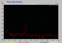
How about considering another test? What about for noise masking of two close together audio frequencies, one higher level, and the other at a lower level?
Please see attachment below for explanatory diagrams.
Hmm, did not get any notify updates... O
Will check this, a nice view would be an 3D spectrum plot of the master clock walks & side jitter signal walks.
look at picture #97 Article: Understanding Digital Audio Measurements | Page 5 | Audio Science Review (ASR) Forum, did some test about PLL & synthesizer master clock based gear
an other is about the dirac impulse swings, I had in the old days a paper, who claimed, a side peak should be below -40dB. But have them any more and google do not help. As in the WADIA days seen, with the spline oversampling.
Hp
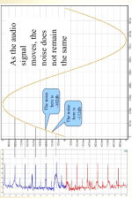
The reason I am interested in noise masking of low level signals possibly due to clock phase noise is I can imagine a lot of conditions in real music where instruments are a little out of tune with each other and or harmonics of instruments are out of with fundamental of another instrument, etc., where small details of the real sound of an instrument or vocal may be masked or not, depending on clock performance. I believe that effect is audible in my laptop soundcard. Sound details seem to fade away into noise so it almost sounds like nothing is missing, but if I play the same wav file on my best dac it sounds like there is little or none of small sound details fading away into gentle sounding noise. Since it kind of sounds that way, seems an interesting thing to be able to measure.
As a side-note on the above, it kind of sounds like the distortion of the laptop soundcard is also almost buried in noise. I seem to recall, maybe it was Ed Simon, who said some designers of consumer audio equipment purposely raise noise levels to mask other defects. The idea was to select resistor values so as to give the desired amount of masking noise.
As a side-note on the above, it kind of sounds like the distortion of the laptop soundcard is also almost buried in noise. I seem to recall, maybe it was Ed Simon, who said some designers of consumer audio equipment purposely raise noise levels to mask other defects. The idea was to select resistor values so as to give the desired amount of masking noise.
Last edited:
hmm,
what base freq. & level and apart freq. & level we are talking about. Just for simulation purpose.
As you see on the spectrum given on the other forum, masking level & freq. apart can be seen.
Analog generators have other phase noise as Vicktor's..
to measure this levels depend best of the coherent signals, so FFT window's can be skipped, otherwise larger FFT is required to go below the window bell
hp
What people often do is average FFTs to reduce displayed noise. Many people seem not to care too much about the noise itself. Rather than ignoring FFT noise, what I have been thinking about a little is that if we had a lower level signal, say, maybe at 1001Hz, and a higher level signal, say, at 1000Hz and we took an FFT to look at the level of the 1001Hz signal relative the phase noise skirts of the 1000Hz signal magnitude, that might be useful to see. To help could clean up the picture some maybe we could try averaging clock skirt phase noise magnitude from successive FFTs (to get a better idea of its potential to mask the lower level 1001Hz signal). Real question is how close in frequency and or different in magnitude do two audio signals have to be for skirt noise masking to affect audibility of the lower level signal? Can it help explain part of what people report hearing when they claim to hear improved audio reproduction from using lower phase noise clocks? Its similar to idea in radar of small return signals being masked by carrier phase noise. Maybe something like that. A more technical treatment of the problem in radar can be found at:https://purehost.bath.ac.uk/ws/port...hase_Noise_Analysis_in_FMCW_Radar_Systems.pdf
Lots more info and modeling in books such as this one: https://www.amazon.com/Phase-Analysis-Systems-Personal-Computers/dp/0471618942
Lots more info and modeling in books such as this one: https://www.amazon.com/Phase-Analysis-Systems-Personal-Computers/dp/0471618942
Last edited:
Attached, using Lynx L22 loop back 1000.0Hz -12dBFS, 1004Hz -96dBFS, BH7 FFT Window, 4M Samples, SR 192kHz
IMHO things could be complicated:
. 1. Instrument plays 1. Har at 1500Hz
. 2. Instrument plays 501Hz, so 3. harmonic would be a 1503Hz
so masking would be really possible if the tone of both instruments changes over time (as they will) and gets within the phase noise
Cheers
Hp
IMHO things could be complicated:
. 1. Instrument plays 1. Har at 1500Hz
. 2. Instrument plays 501Hz, so 3. harmonic would be a 1503Hz
so masking would be really possible if the tone of both instruments changes over time (as they will) and gets within the phase noise
Cheers
Hp
Attachments
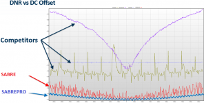
I have seen some DNR graphs dependent of various ESS competitor given from Martin Mallinson ESS.. and currently have no glue how they made this graphs...
Look at given pictures and orange rectangle...
Hp
These are interesting data. They measure AC noise at different DC level. The noise level at higher DC level generally increases due to voltage reference noise. The peaks at particular values are switching noise, I would think they are primarily present in R-2R type DACs.
I am curious if anyone made noise spectrum measurements (not just total DNR) at different DC levels. It can help identify the noise spectrum of the voltage reference. For example, different bypass capacitors would lead to different spectrum.
Noise levels changing with dac DC output level in sigma-delta dacs tend to be caused by the modulator that frequency shapes switching noise so it is mostly outside of the audio band. Spurs seen in such testing are likely another issue from the modulator called idle tones.
https://www.eecs.qmul.ac.uk/~josh/documents/2007/PerezReiss-AES122.pdf
Changing the reference voltage is another matter entirely.
https://www.eecs.qmul.ac.uk/~josh/documents/2007/PerezReiss-AES122.pdf
Changing the reference voltage is another matter entirely.
Last edited:
Thanks for posting an interesting reference. My understanding is that in latest DACs these digital modulation issues have been mostly solved, hence SABREPRO shows fairly flat shape as a function of DC. But the analog issues, like the stability of the voltage references, is still up to the designer.
Its not only the stability and noise of the reference, its how it sounds when its other characteristics are more or less imprinted upon the dac analog outputs. Output impedance verses frequency verses current draw, phase response, nonlinearity, layout, output capacitor characteristics (if the design uses one), etc.
Only way to find out for oneself is to experiment and see what happens.
Only way to find out for oneself is to experiment and see what happens.
Last edited:
- Home
- Source & Line
- Digital Line Level
- ESS Sabre Reference DAC (8-channel)