That can also be done, provided that the 3.3V is sufficient to guarantee a high level on logic with 5V supply (if present). But then it would be easier to just connect the pull-up resistors to 3.3V instead of 5V.
Funnily enough the voltage range of 5V tolerant inputs is specified in the ES9018 data sheet. But it is not specified which inputs have this 5V tolerance
Funnily enough the voltage range of 5V tolerant inputs is specified in the ES9018 data sheet. But it is not specified which inputs have this 5V tolerance
As far as I can see in the atmega2560 data sheet (page 242), the pull-ups can be enabled. If you disable them I assume that you could eliminate the problem. But I have not studied the data sheet in all details, so I am not sure if things can be done in the right sequence to avoid the internal pull-ups entirely.
The internal pull up resistors seem to have a value between 20 and 50kohm, which will not be sufficient in all cases anyway, especially if you run it at full speed. If you connect some 1k or 2k2 resistors to 3.3V, the voltage will be close to 3.3V, no matter if the internal resistors are enabled or not. So we're more or less done
The internal pull up resistors seem to have a value between 20 and 50kohm, which will not be sufficient in all cases anyway, especially if you run it at full speed. If you connect some 1k or 2k2 resistors to 3.3V, the voltage will be close to 3.3V, no matter if the internal resistors are enabled or not. So we're more or less done
 ) - pending.
Troubles setting 7 8 9 bits Quantizer
Hello,
I am playing with BII and I am finding some trouble setting the Quantizer.
I wrote my code from zero, but basing everything of the code from hifiduino.
DAC2/4/6/8 and DAC1/3/5/7 are phisically paralled on the PCB, and, by the firware setup, the inputs are DAC3=DAC1 DAC7=DAC5 DAC4=DAC2 DAC8=DAC6 meanwhile from the phisical point of view I have SPDIFs inputs on DATA3 DATA7 and DATA8, IIS&DSD shares DATA1 DATA2 DATA4 DATA5 and DATA6. Played a little on the BII.
Everything works fine but I have some troubles understanding how the quantizer works.
The ES9018s register #15 manages this setup and it is well explained here https://hifiduino.wordpress.com/sabre32/ (see the description of Reg15). Everything started from the explanation by dusfor99, really the father of this DAC, http://www.diyaudio.com/forums/digital-line-level/117238-ess-sabre-reference-dac-8-channel.html#post1429418.
Frankly speaking I didn't understand the explanation by dusfor99 so I ask a help to understand why the behaviour of my setup.
The behaviour is the same for SPDIF, 3 different inputs, and IIS.
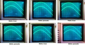
6bits true - the output is as expected.
7bits pseudo - the output is as expected.
8bits true - a degradation is starting. Means distortion.
8bits pseudo - degradiation remains but with adiffrent spectrum.
8bits true - still degradation. Increased.
9bits pseudo - better than 8bit true but still impossible to accept.
What is really curious is only one channel has this trouble. The channel resulting by DAC2+DAC4+DAC6+DAC8.
I would like to understand why.
Mainly I didn't understand the explanation of how the quantizer works.
So I don't know how to explain the behaviour.
I know in the data sheet is written to set the Reg15 to 0x00, mean 6 bits true, to have the best results about THD&N ... but I would like to understand.
Thanks for any help.
I attach the pictures of the oscilloscope traces. It is for 200Hz tone. Same story with 1KHz tone. Nothing change.
I have also the pictures of the FFT for each state where it is clear the huge amount of distortion coming when on the oscilloscope the saw trace starts.
Hello,
I am playing with BII and I am finding some trouble setting the Quantizer.
I wrote my code from zero, but basing everything of the code from hifiduino.
DAC2/4/6/8 and DAC1/3/5/7 are phisically paralled on the PCB, and, by the firware setup, the inputs are DAC3=DAC1 DAC7=DAC5 DAC4=DAC2 DAC8=DAC6 meanwhile from the phisical point of view I have SPDIFs inputs on DATA3 DATA7 and DATA8, IIS&DSD shares DATA1 DATA2 DATA4 DATA5 and DATA6. Played a little on the BII.
Everything works fine but I have some troubles understanding how the quantizer works.
The ES9018s register #15 manages this setup and it is well explained here https://hifiduino.wordpress.com/sabre32/ (see the description of Reg15). Everything started from the explanation by dusfor99, really the father of this DAC, http://www.diyaudio.com/forums/digital-line-level/117238-ess-sabre-reference-dac-8-channel.html#post1429418.
Frankly speaking I didn't understand the explanation by dusfor99 so I ask a help to understand why the behaviour of my setup.
The behaviour is the same for SPDIF, 3 different inputs, and IIS.
6bits true - the output is as expected.
7bits pseudo - the output is as expected.
8bits true - a degradation is starting. Means distortion.
8bits pseudo - degradiation remains but with adiffrent spectrum.
8bits true - still degradation. Increased.
9bits pseudo - better than 8bit true but still impossible to accept.
What is really curious is only one channel has this trouble. The channel resulting by DAC2+DAC4+DAC6+DAC8.
I would like to understand why.
Mainly I didn't understand the explanation of how the quantizer works.
So I don't know how to explain the behaviour.
I know in the data sheet is written to set the Reg15 to 0x00, mean 6 bits true, to have the best results about THD&N ... but I would like to understand.
Thanks for any help.
I attach the pictures of the oscilloscope traces. It is for 200Hz tone. Same story with 1KHz tone. Nothing change.
I have also the pictures of the FFT for each state where it is clear the huge amount of distortion coming when on the oscilloscope the saw trace starts.
Attachments
Checked more than one time.
After I wrote the registers inside the ES9018s I read them and printed on the LCD. So I have the continuos check of all the registers.
Changing the Quantizer bits only register 14 and 15 change. Register 14 changes only bit#3, and Register 15 changed from 00 to 55 to AA and to FF. Nothing more.
And by hardware as known DAC2 DAC4 DAC6 DAC8 phisically together and the same for DACB2 DACB4 DACB6 DACB8. Set the register for the polarity in phase and anti-phase exactly like the DAC1 DAC3 DAC5 DAC7 and DACB1 DACB3 DACB5 DACB7 side. All the same.
The "odd" channel works very well. The "even" channels works well only for 6bits true, 7bits pseudo and then for 7bits-true 8bits-pseudo 8bits-true 9bits-pseudo a distortion appear.
Checking by the FFT (CLIO) the distortion is made of multiple of the tone frequency under test. So some channels have the phase inverted. And not always the same. ... but is the registers don't change but only as I said .... ????
How is it possible?
the firmware "can't be" because the register are printed on LCD the full time, and nothing changes but the 2 interested reg14 and reg15.
the harwdware works well for 6bits and 7 bits and the distortion (really multiple frequencies of the test tone) comes on the upper quantization. And only for the odd channel.
... where can I investigate?
The chip is set up in stereo mode, DACx in phase DACBx in anti-phase. And never changes.
... where can be the mistake? What can I exclude?
By hardware the chip works in true differential mode. And DACx and DACBx are set to work in this way.
Is possible to set the bit depth of the quantizer not involving in phase troubles?
Reading this http://www.diyaudio.com/forums/digital-line-level/117238-ess-sabre-reference-dac-8-channel.html#post1429418 seems the phase changes when I change the bits depht .... but frankly speaking the content of the thread #35 just linked is not clear for me.
Any help is appreciated.
.... probably a stupid mistake so big to don't see it.
What can I exclude as sure?
Thanks.
To my regret, I have no idea on the cause of your problem.
I hope my previous post showing my interpretation on a quantizer bit depth may help you.
http://www.diyaudio.com/forums/digi...-reference-dac-8-channel-240.html#post4072152
I hope my previous post showing my interpretation on a quantizer bit depth may help you.
http://www.diyaudio.com/forums/digi...-reference-dac-8-channel-240.html#post4072152
... found the explanation of what's happen
https://hifiduino.wordpress.com/2011/05/30/buffalo2-sabre32-dac-mega-test-2/
... and now the #35 is more clear: a hardware wiring of the pins of ES9018s goes in competition with the firware "wiring" imposed when you set the quantizer.
Isn't it? Can somebody confirm if I am on the right way?
https://hifiduino.wordpress.com/2011/05/30/buffalo2-sabre32-dac-mega-test-2/
... and now the #35 is more clear: a hardware wiring of the pins of ES9018s goes in competition with the firware "wiring" imposed when you set the quantizer.
Isn't it? Can somebody confirm if I am on the right way?
yes, it does.
Even if in SPDIF mode, with the signal locked, if I change from 6bits true or 7bits pseudo to 7bits true or 8/9 bits the distortion comes.
If I use a tone to test the DAC, 1KHz ofr example, by FFT I see the distorion is made of mutliple of 1 KHz test tone.
The SPDIF signal comes through DATA 3 or DATA 7 or DATA 8.
Ciao
I found the time to study the Quantizer of the ES9018s.
DATA3 DATA4 DATA7 and DATA8 are "disconnected" when in 8 bits mode. More, in 9 bit mode also DATA5 and DATA6 are "off".
I entered the SPDIF to DATA3, so it is explained why I have distortion if I use the 8 or 9 bits quantizer. ... but if DATA3 is disconnected, why I have a distorted output instead of nothing? Does "disconnected" means "do not use" or "do not connect"?
More. What it is not clear for me is why with a i2S, using the Buffalo II wiring, so using DATA1, DATA2, and DATA2 wired to DATA4 too, should be possible to use the 8 or 9 bit quantizer. DATA4 is "off". I read some tests sessions made with BII and the Quantizer set to 8 or 9 bit. I hear distortiont if in i2S and 8bit or 9bit mode.
Only the DSD is the candidate to experiment the 8bit quantizer because in BII the DSD input is wired DATA1 DATA2 DATA5 and DATA6. But I hadn't tried it yet.
Isn't it? Somebody can help me?
Does anyone have any idea on an expected actual product launch date of this new flagship Sabre DAC chip, ES9038PRO?
ESS Technology :: ESS Technology Introduces the SABRE PRO Series of DACs Setting a New Performance Bar with Unprecedented 140 dB Dynamic Range
I really hope it will provides a "Quick lock with synchronous MCLK" that ES9018 K2M revision V supports.
ESS Technology :: ESS Technology Introduces the SABRE PRO Series of DACs Setting a New Performance Bar with Unprecedented 140 dB Dynamic Range
I really hope it will provides a "Quick lock with synchronous MCLK" that ES9018 K2M revision V supports.
- Home
- Source & Line
- Digital Line Level
- ESS Sabre Reference DAC (8-channel)