I wonder...
What to set the PLL BW to if you have a very good clock. Obviously, a PLL tries to sync an *internal* clock to the incoming clock frequency wise. This is all good if the incoming clock has worse jitter than the internal one. But if the external is better than the internal? Would it make sense to set the PLL to wide in order to let the external clock rule rather than the internal?
Whats the difference between Reg #25 and Reg 17(5), Reg #11 (No BW) and Reg #10(2)?
//
Hi, TNT!
I assume you are considering not ES9018 K2M Rev. V but ES9018S.
First, my speculation on ES9018 architecture is;
1. There is no "internal clock". Rather, there is a basic 32 bit integer counter that is counted up by an external MCLK.
2. The chip must determine the output timing of in-coming data based on the time scale of the counter value. A mechanism implemented for this purpose could be a "DPLL".
It might be nothing to do with "Jitter Eliminator" functionality.
We can't stop the DPLL mechanism while we can stop the "Jitter Eliminator".
3. "DPLL bandwidth" might be defined as an allowable range of counting value fluctuation.
Based on my experiences, I can definitely say "a synchronous master clocking scheme" brings better sound quality as far as you apply a good BCLK(I2S) signal.
Does this explanation make sense to you?
Sure - thanks!
I have the Acko Dac with ES9012 and the clock/buffer from Ian. Yes, I suspected that a DPLL might not utilize an actual clock. I suppose it is then a digital flywheel of some sort!? I run MCLK with a 5 cm u.fl cable from clock to DA board.
I have not managed to make register read/write working but I can use the built in commands of the Acko controller to manipulate PLL BW. I feel that the wide setting (described as less jitter suppressing) sounds maybe better - less harsh/edgy. But also some definition is lost... fine differences...
//
As far as I have experienced, I think effective changes in a clock domain tend to bring improvements in all frequency ranges.
In bass range, I feel it gets less boomy and more controlled. (I'm sorry that my vocabulary in Engish is not good enough!)
When you say less boomy and more controlled , would you say it is more punchy or has greater impact in the lower regions.
.....
I have not managed to make register read/write working but I can use the built in commands of the Acko controller .....
Have you checked the actual DAC I2C address in direct register mode? This is not the same as the remapped address (0 or 1) as presented by the controller for function commands
Last edited:
Have you checked the actual DAC I2C address in direct register mode? This is not the same as the remapped address (0 or 1) as presented by the controller for function commands
@TNT in addition to Acko's comment above, also be careful about the 8bit vs 7bit i2c address the 8th bit is for direction (read/write) and is often managed by the i2s library. What are you using for i2c comms direct instead of Acko's controller?
When you say less boomy and more controlled , would you say it is more punchy or has greater impact in the lower regions.
My impression is "less punchy" or "less impact". However, more clear, easier to recognize and more impressive.
By the way, I think we need to specify musical instruments when we discuss bass.
Hi Excelon,
Yes you can bypass the internal upsampler if you like. You can put data in at 8X. X can be up to 192k. So that means its possible to put data into the chip at 1.536MS/s. Now that would require a 98.304MHz bit clock (64*8*192k), but the chip will do it if your not worried about running those kinds of clocks and data on an audio board.
Dustin
Hi Dustin,
It seems that you've not been log on diyaudio for a long time. I post my question here in case you come here again later or ...
It it no double that ES9018 has the noise bumping issue in every chip. No matter which I/V you use, discrete or OPAMP or tue (if you can done a tube output stage which can deliver ~1.5uV rms noise in audio band).
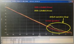
But in fact, the chip can work normally in some way. (I am not sure about the root cause and corresponding solution) Please find the measurement below:
the yellow curve is the default working condition, in this way ES9018 diliver ~129dB DNR in my bench. But most important thing is that the THD+N is a little poor in the range -10dBFS to -36dBFS. When I dig it deeper, I found that the THD is not the issue, but the noise floor.
the red curve is the normal operation which I expect from ES9018. It delivers 130dB DNR and excellent THD+N in the full output range. Further check on this working condition, the whole system provide amazing linearity up to +/-1 ~2 dB error in -140dBFS to 150dBFS range.
I think all the user want to get the second operation condition from ES9018. Will you share your comment on this question?
Thank you in advance.
")
BR
Paul Lu
Attachments
Hi Dustin,
It seems that you've not been log on diyaudio for a long time. I post my question here in case you come here again later or ...
It it no double that ES9018 has the noise bumping issue in every chip. No matter which I/V you use, discrete or OPAMP or tue (if you can done a tube output stage which can deliver ~1.5uV rms noise in audio band).
But in fact, the chip can work normally in some way. (I am not sure about the root cause and corresponding solution) Please find the measurement below:

the yellow curve is the default working condition, in this way ES9018 diliver ~129dB DNR in my bench. But most important thing is that the THD+N is a little poor in the range -10dBFS to -36dBFS. When I dig it deeper, I found that the THD is not the issue, but the noise floor.
the red curve is the normal operation which I expect from ES9018. It delivers 130dB DNR and excellent THD+N in the full output range. Further check on this working condition, the whole system provide amazing linearity up to +/-1 ~2 dB error in -140dBFS to 150dBFS range.
I think all the user want to get the second operation condition from ES9018. Will you share your comment on this question?
Thank you in advance.
BR
Paul Lu
Hello
Do you know if the ES9018K2M also suffers from this bug or "working condition"? or is only for the first ES9018 version?
Very thanks.
Anyone have any idea how to debug this chip?
I have a working device and made another, exactly the same, but it turns on, locks to the spdif signal, but after 10 seconds it drops it and never locks again. Have to turn it off, wait a bit and back on.
Is there a way to get some info out of the chip? Why it can't lock?
I have a working device and made another, exactly the same, but it turns on, locks to the spdif signal, but after 10 seconds it drops it and never locks again. Have to turn it off, wait a bit and back on.
Is there a way to get some info out of the chip? Why it can't lock?
Hi, mrWagner!
I'm afraid that your question is too vague to be answered.
Are you using a MCU to set registers of your DAC chip via I2C?
How have you set those registers before you make your experiments?
I think it's better for you to explain your current conditions more in details.
My guess is, your DPLL setting is too strict for your condition.
Bunpei
I'm very sorry for asking this question on this thread before I try it actually by myself. I have currently no environment for attempting this register writing operation for my ES9018 DAC at my hand.
My question is;
When an I2S input is applied and a rigid lock is maintained under a certain condition, how does such a register bit assertion as dpll_lock_rst_reg=1 (Manually override the dpll_lock, Register #17: Mode Control 5) affect output audio sound? Does it bring a short unlock state and an immediate interrupt of audio signal or no interrupt?
Hi, mrWagner!
I'm afraid that your question is too vague to be answered.
Are you using a MCU to set registers of your DAC chip via I2C?
How have you set those registers before you make your experiments?
I think it's better for you to explain your current conditions more in details.
My guess is, your DPLL setting is too strict for your condition.
Bunpei
On my working chip I have I2C connected to it, but on the problematic one it is not connected yet, so everything is factory default.
I have one working chip and 2 not working. The one I talked about works for about 10-20 sec (today worked for about 40 sec) after turn on, then shuts the output, as the output goes to 0 insted of half voltage.
And there is the second not working one, where the I2C works, but setting DPLL didn't help. It only lights up the lock led for about 1 sec, then shuts the output down.
I don't think it is DPLL problem as while it works, works perfectly. No crack, no tiny lock problem, then just shuts down after random time.
The strange thing is that the first built one works perfectly, but the others don't.
That is why I would like to know if there is any way to get info out of the chip and not just configure it's settings.
1. Did you hand-soldered your DAC chips on your board? Was the soldering done uniformly without any heat damage?
2. Is the DAC device reset in a proper manner after power on? What behavior do you observe after you manually reset the chip later? Do you have a temporary sound of short duration after the manual reset?
3. How do you connect your input to the DAC device? Is a ground line connected in a secured manner?
4. Are all the necessary powers actually supplied to the chip? Have you checked power voltages?
5. Do you have a datasheet and know contents of DAC status registers? Do you have an I2C host to read the registers?
We also went towards the mute/reset section and turned out that the reset leg was not conencted to earth as we souldered as few parts as possible to exclude problems. Now it seems to work and not turn off after a while. So the 3rd device is working fine. Simple and rather stupid mistake.
Second device may be damaged as one of it's 1.2V imputs got 2V for a while and it may have done some damage. It's analog output to be precise.
It is a ES9018 chip, I can read I2C from it, but didn't find any good register to read. There are only usefull registers for a working device, to configure the chip, not to debug it.
I measured the voltages on it's legs and seem to have everything as it should. Chip was soldered by a competent guy, others were done by me.
Input comes through optic, so earth not connected to external devices.
Next will be to check also the reset leg, maybe it also has the problem there.
But still would like to know if there is any usefull register to read from a ES9018 chip, to know why it shuts down the outputs.
- Home
- Source & Line
- Digital Line Level
- ESS Sabre Reference DAC (8-channel)