High Voltage
Hi,
Do yourself a favor.
Isolate the High Voltage strip it may NOT come in contact with wood!
Wood conduct if you have high humidity and high voltage so you don't want your element/frame to be charged! happen to me when I made my frame with wood.
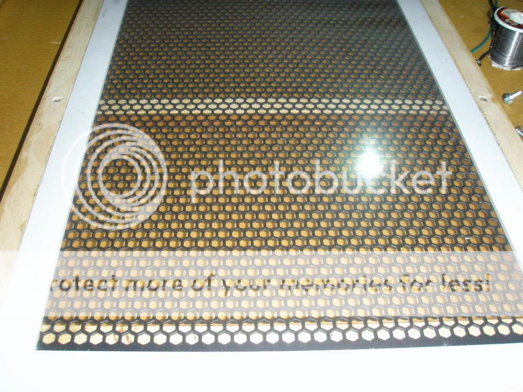
Your plate looks nice, I tried this also and was difficult to isolate due to the sharp point of the hexagon hole. For DIY it's OK but be aware not to touch it when playing music. Looks nice !
Just my 2 cents.
Best regards,
Audiofanatic")
Hi,
Do yourself a favor.
Isolate the High Voltage strip it may NOT come in contact with wood!
Wood conduct if you have high humidity and high voltage so you don't want your element/frame to be charged! happen to me when I made my frame with wood.
Your plate looks nice, I tried this also and was difficult to isolate due to the sharp point of the hexagon hole. For DIY it's OK but be aware not to touch it when playing music. Looks nice !
Just my 2 cents.
Best regards,
Audiofanatic
i just discoverd that techspray has a new type of spray called licron crystal clear has anybody used this product?acording to them it is transparent unlike the original licron.jer
read back and search - it has already been discussed, perhaps earlier in this thread or one like it.
_-_-bear
Hi,
Do yourself a favor.
Isolate the High Voltage strip it may NOT come in contact with wood!
Wood conduct if you have high humidity and high voltage so you don't want your element/frame to be charged! happen to me when I made my frame with wood.
Your plate looks nice, I tried this also and was difficult to isolate due to the sharp point of the hexagon hole. For DIY it's OK but be aware not to touch it when playing music. Looks nice !
Just my 2 cents.
Best regards,
Audiofanatic
Hi Audiofanatic,
Thanks for your advice. No, I do not let my high voltage copper strip touches the wood. I put a double insulation on the wire and make sure that the copper won't touch the wood.
I personally find that the sharp points on these hexagon holes are way less than the round holes. In fact I don't seem to find it anywhere.
I will always be careful not to touch the stators when playing music. But I once unintentionally touched both stators.
 Luckily, nothing happens. I will not do that again. I am thinking that I will put a grill on front and back.
 Wachara C.
thanks bear,i have been meaning to do some more searching.i have been using the old stuff but not the new,as i didn't know there was a new formula until three days ago.nice pics wachara C. i have been practicing on some scrap pieces and i need to build some new frames,but i'll have the tiny driver rebuilt in a few days or so.i'll keep you all posted when i have some resuls. jer
Hi,
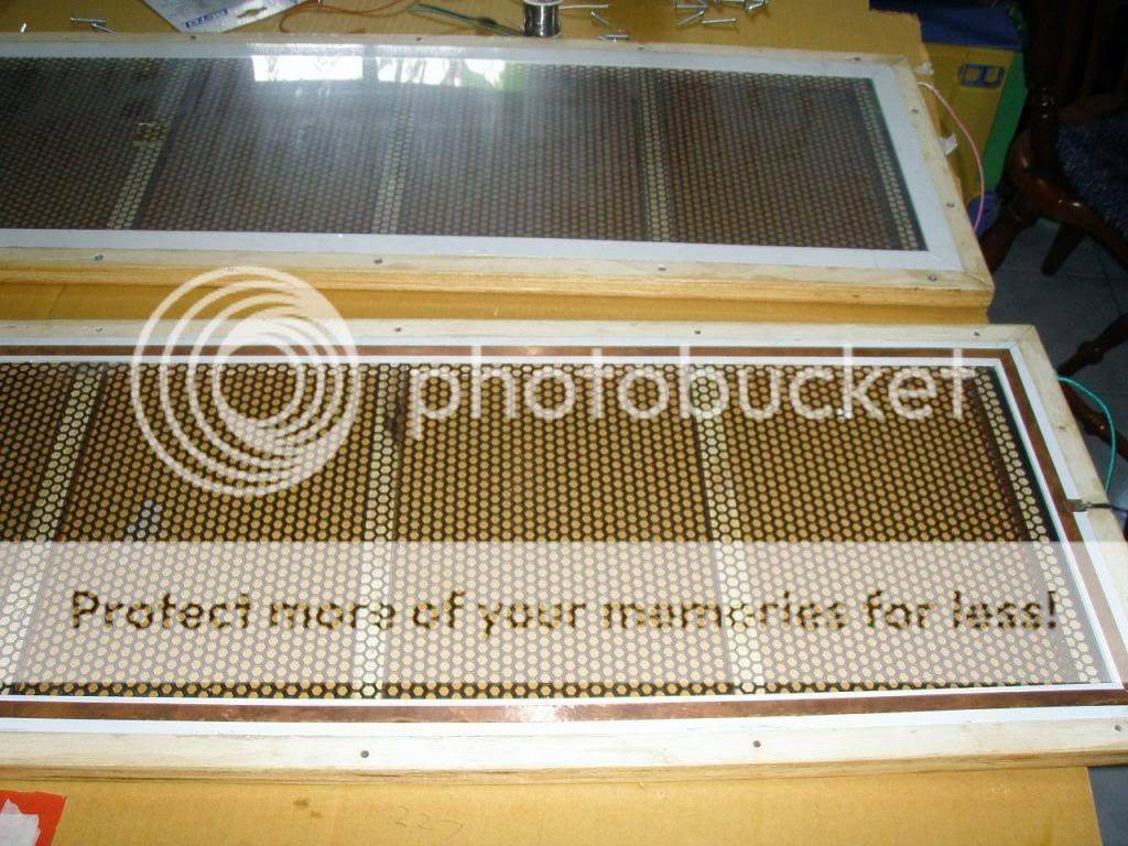
good idea to make the thing detachable. There are two good reasons:
- The stator coating looks very thin. While this is indeed optically pleasing it is not so in a technical way. "Don´t touch it", is a healthy advice I´m afraid the panel will be prone to arcing.
- Sheesh....miles of d/s spacing again *lol* It seems to be somehow delightful to build inefficient panels and complain later on that things don´t work as well as intended.
jauu
Calvin
good idea to make the thing detachable. There are two good reasons:
- The stator coating looks very thin. While this is indeed optically pleasing it is not so in a technical way. "Don´t touch it", is a healthy advice
I´m afraid the panel will be prone to arcing.- Sheesh....miles of d/s spacing again *lol* It seems to be somehow delightful to build inefficient panels and complain later on that things don´t work as well as intended.
jauu
Calvin
Hi,
good idea to make the thing detachable. There are two good reasons:
- The stator coating looks very thin. While this is indeed optically pleasing it is not so in a technical way. "Don´t touch it", is a healthy advice
- Sheesh....miles of d/s spacing again *lol* It seems to be somehow delightful to build inefficient panels and complain later on that things don´t work as well as intended.
jauu
Calvin
Hi Calvin,
Go ahead, laugh all you want.
The reason why I posted these pictures is that I don't want our friends on this forum to get a wrong idea that after using PVA glue coating, the diaphragm will look dull. The coating should be very thin and transparent with only a slight change in color.
I know that you like the smallest possible spacer, but for me, I just want to see how much difference it would be between using 1mm, 1.5 mm, 2 mm, and 3 mm spacers. In fact, I have tried them all.
There is no better way to learn than actually trying it, right? Wachara C.
3 millimeters isn't to bad, considering Quad Esl63= 2.5 mm, Audiostatic = 4 mm, Acoustat= 2.7 mm, M-L CLS = 3 mm. These are figures that I've measured when repairing those speakers...
But there is a point in Calvins statement, trying to keep the distance as small as possible.
Martin Logan flagship model CLX have about 2 mm in their 3-stator basspanel.
But there is a point in Calvins statement, trying to keep the distance as small as possible.
Martin Logan flagship model CLX have about 2 mm in their 3-stator basspanel.
Jonas !
Hi Jonas and other fellow members,
Jonas, you're right! This is not bad/wrong to have a distance of 3mm. I have on a prototype a distance of 4.5 & 5 mm. It works perfectly ! The only thing you have to worry about (in such case) is the step-up ratio use at least 1:150 otherwise you'll miss a whole lot!
BTW Jonas, nice quote
Best regards,
Audiofanatic
3 millimeters isn't to bad, considering Quad Esl63= 2.5 mm, Audiostatic = 4 mm, Acoustat= 2.7 mm, M-L CLS = 3 mm. These are figures that I've measured when repairing those speakers...
But there is a point in Calvins statement, trying to keep the distance as small as possible.
Martin Logan flagship model CLX have about 2 mm in their 3-stator basspanel.
Hi Jonas and other fellow members,
Jonas, you're right! This is not bad/wrong to have a distance of 3mm. I have on a prototype a distance of 4.5 & 5 mm. It works perfectly ! The only thing you have to worry about (in such case) is the step-up ratio use at least 1:150 otherwise you'll miss a whole lot!
BTW Jonas, nice quote
Best regards,
Audiofanatic
i agree as as even my 4.5' wide panels somtimes bottom out with .0625" spacers and especialy the 9" wide panel with any peaks below 200 hz.i now use .090" on those panels when driving them fullrange, the defficiency in sensitivty (or least most of it) was made up with a higher bais .once i pushed the bias to the 7kv to 10kv range and the sensitivity was incredible,but of course all kinds of nasty things started to happen,arcing,poping,holes burned in the diagphram and transfromers breaking down.luckly my amp held up. jer
Hi,
for a FR even 3mm might be acceptable but no more. More will work somehow, but definitely far from perfect! The reason simply beeing that all voltages involved rate at such high levels that performance is seriously degraded. Transformers with lower Us are better -measurable as well as sonical. Insulations which can be specced with lower ratings can be thinner, can be better/safer and last longer. Losses are lower, Power demands are considerably lower. Amps are less stressed. Eventual arcs burn with lower energy (less hot). Distortion values get much higher. Frequnecy response becomes less linear and needs more equing, etc. etc.
What do You gain when increasing Stator-stator-distance instead??? Typically not much, quite often nothing at all, because the increased s/s-distance is most often used to lower membrane tension as well to lower the resonance frequency and to increase the Q of the resonance (which needs to be increased to counter for the additional phase cancellation at lower freqs.). This leads to an increased offset (depending on the force introduced by the bias voltage) so that the d/s is not necessarily larger than with a higher tension lower voltage design. In fact the lower tension design will arc over much quicker or the membrane touches the stator at already much lower SPLs.
It should be understood that increasing s/s and lowering fs does not worsen important specs linearly but rather quadratically.
jauu
Calvin
i have generaly find around 1:50 spacing/width or less good for mid/tweeter panels and 1:100 a pretty good ballpark figure for fullrange,but what if you wanted to build a wider panel say 18" or 24" ,12" is already pushing the limit to 1/8" imo it is to much.i know this is off subject but since it is being discussed,what are some feasible proven limits?
3 millimeters isn't to bad, considering Quad Esl63= 2.5 mm, Audiostatic = 4 mm, Acoustat= 2.7 mm, M-L CLS = 3 mm. These are figures that I've measured when repairing those speakers...
But there is a point in Calvins statement, trying to keep the distance as small as possible.
Martin Logan flagship model CLX have about 2 mm in their 3-stator basspanel.
Hi JonasKarud,
Thanks for sharing the infos. Do you happen to know what transformer step up ratios they use as well?
Wachara C.
From memory :
QuadEsl63: 2 times 1:125, I have actually unwinded and rewinded(not so funny, nor easy) one of those, it had 50 primturns....
Acoustat: 1:200 bass transformer, 1:60 treble tranny.
Martin Logan CLS: I don't know, but looking at the impedance plot, I guess around 1:120...
QuadEsl63: 2 times 1:125, I have actually unwinded and rewinded(not so funny, nor easy) one of those, it had 50 primturns....
Acoustat: 1:200 bass transformer, 1:60 treble tranny.
Martin Logan CLS: I don't know, but looking at the impedance plot, I guess around 1:120...
Hi JonasKarud,
Thanks for the info. I have tried a few transformers, and I have found that the higher the turn ratio, the more difficult for the transformers to do good sound especially in high frequencies. I guess it must be the internal capacitance of the transformer that is the problem.
Can you share with us how the QuadESL63's transformer is wound? I guess it must have many layers of interleaving.
Wachara C.
Hi,
The higher the ratio the more complex the tranny has to be wound and the more difficult it gets to keep parameters on the side of light. So either the bandwidth of the ESL is far below the audio bandwidth or the effective membrane area must become small.
The former leads to a multiple way speaker which needs crossover circuitry, the latter leads to a multiple way speaker with crossover circuitry and seriously spoiled dynamic range.
Don´t You wonder why all those high-U ESLs sound so boring like sleeping pills, lacking seriously in dynamics? Extremely high values >>1:100 are nothing else but a major conceptual flaw of the design. Such thingies will never be able to show the true sonic potential a decent designed ESL is capable of.
jauu
Calvin
Exactly. Why do You think do Tube amp developers strive for a rather low U (seldom beyond 20:1).the higher the turn ratio, the more difficult for the transformers to do good sound
The higher the ratio the more complex the tranny has to be wound and the more difficult it gets to keep parameters on the side of light. So either the bandwidth of the ESL is far below the audio bandwidth or the effective membrane area must become small.The former leads to a multiple way speaker which needs crossover circuitry, the latter leads to a multiple way speaker with crossover circuitry and seriously spoiled dynamic range.
Don´t You wonder why all those high-U ESLs sound so boring like sleeping pills, lacking seriously in dynamics? Extremely high values >>1:100 are nothing else but a major conceptual flaw of the design. Such thingies will never be able to show the true sonic potential a decent designed ESL is capable of.
jauu
Calvin
Hi JonasKarud,
Thanks for the info. I have tried a few transformers, and I have found that the higher the turn ratio, the more difficult for the transformers to do good sound especially in high frequencies. I guess it must be the internal capacitance of the transformer that is the problem.
Can you share with us how the QuadESL63's transformer is wound? I guess it must have many layers of interleaving.
Wachara C.
I've found my notes from when I unwound this transformer!
Surprisingly there was no interleaving, the windings began with 49 prim turns closest to to the core, followed by 42 secondary layers, each layer having a random number of windings of 100 to 171.
The sequence was (from core and out wards):166,123,132,151,135,150,136,141,140 and so on. (Please, don't ask me for the whole sequence!)
Total number of secondary winding turns was 5868, which gives a step up of
roughly 1:120.
The C-core iron area was two times 51x13.4 mm = 1367 square mm, iron path
lenght about 200 mm.
There is a possibilty that my notes about the random secondary turns that it is my notes that are random. Counting to 166, write it down, count to 123, write it down und so weiter. In this case, forget the number of secondary layers.
Last edited:
- Home
- Loudspeakers
- Planars & Exotics
- ESL Diaphragm coating