i am in for 2 ps pcb's as well. in the original signup sheet there was a column for the ps pcbs and there were 50-60 requested at that time. I have not received my dac pcbs as i was one of the group that requested combined shipping with the ps pcb. i assumed that was still in process?
I don't mean to be difficult or unpleasant - though sometimes I can't help it. I don't agree that it's my fault for not looking on a thread titled "ES9023 / WM8804 S/PDIF DAC Parts GB EU Only" for a power supply board in the US. And if I had, I couldn't have gotten in on it anyway.
Anyway, I'm glad Subbu will do a group buy which I can get in on. And if he isn't, I'll volunteer. I've ran a group buy before.
As far as finished boards: I finished one of my two. I noticed Jean-paul wrote that it can be built in about 1 hour. It took me 4 evenings listening to at least 2 CD's each evening. I think I'm just slow. The Elliott Sound Products manuals always say "The project can be completed by an experienced hobbyist in about 1 hour." I'm an experienced hobbyist, and I've never finished one of his boards in less than 4 hours.
Now, if I only had a power supply . . .

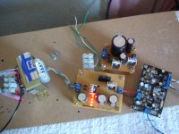
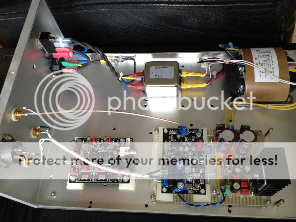
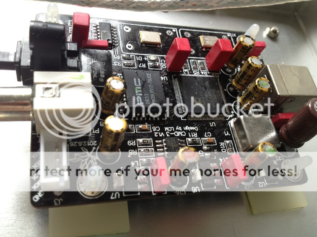
Now ByronInLawrence, that is what I call tidy work. Better slow work than bad work. Neatly soldered, just a tad too much on the ES9023, R6 and R12 but solder wick is a friend of you too. I miss the connector, use a good one there like the ones from Phoenix. And EUVL (Patrick) was right on the MKP/FKP caps for the 2 x 4.7 nF as they are just a bit better. Don't tell him as I hate it when I am eh wrong. I tried ERO KS (polystyrene) and liked it too. You are officially in the league of fearless DAC builders now. Just don't start on 78XX ! It is that Buzzforb is very busy with his project now otherwise that picture would have been a good motivation to him spending money, blood, sweat and tears on his project.
I don't want to start confusion but you could try :
- a 4.7 µF tantalium cap for C8 , check the polarity. I changed that one to 1 µF PPS and 1210 footprint earlier but it did not make it to the BOM.
- C32 can be a 4.7 µF Pana FC. Try it on the second DAC and compare with the other one.
Now the mother of all questions:how does it sound even without the filter caps ? And get in touch with our secretary, the lovely blonde one with razorsharp pumps and golden ears. She will be leading you through the chaos called group buy.
Last edited:
Byron,I don't mean to be difficult or unpleasant - though sometimes I can't help it. I don't agree that it's my fault for not looking on a thread titled "ES9023 / WM8804 S/PDIF DAC Parts GB EU Only" for a power supply board in the US. And if I had, I couldn't have gotten in on it anyway.
Anyway, I'm glad Subbu will do a group buy which I can get in on. And if he isn't, I'll volunteer. I've ran a group buy before.
As far as finished boards: I finished one of my two. I noticed Jean-paul wrote that it can be built in about 1 hour. It took me 4 evenings listening to at least 2 CD's each evening. I think I'm just slow. The Elliott Sound Products manuals always say "The project can be completed by an experienced hobbyist in about 1 hour." I'm an experienced hobbyist, and I've never finished one of his boards in less than 4 hours.
Now, if I only had a power supply . . .
I have built 2 regulated 5V supply based on the PFM and the 3 pin regulator concept of Just one thing about music - when it hits you feel no pain. I don't have a scope to measure (I should say, I have a HP 100Mhz scope but haven't quite figured out how to use it
 ) how low noise they are, but according to Martin's measurement, they should be very very good.
If you are desperate to test your dac
, PM or email me via the forum. I will sell one of them at the cost of the parts, shipping, plus the cost of an European Import beer It requires a 9-0-9 or above transformer as it uses full wave rectification. I have extra transformer like the one in the picture,it is a 18VAC CT at 1.5A. Attached is a picture of both.BTW, the EU GB is only parts, no PCB, FWIW.
Attachments
Hey you should be working on your project ! You feel at home cause you are at home making a DAC Buzzforb. You will be decorated later after your DAC is ready.
Pchw, if it is the Flea you have built I can tell that is a truly excellent design. I have made several of those for XO's and I love them except for the very high input voltage they need. Nothing can be perfect. It is low current though but you used the extra pass transistor I think ? If so max current is too close to the current the DAC board consumes.
BTW Ray sells very good PCBs and kits for the PFM Flea. These small devices are very good for low jitter clock devices like Tent XO or 7 x 5 low jitter XO's like those from Fox etc. Just change 2 resistors to have it put out 3.3 V for modern devices:
www.raylectronics.nl
Last edited:
Hi JP,
No, it is not the flea. It is more like the first part of the flea, I think it is called the Regulator booster. It is simply a mosfet based capacitance multiplier in front of a On-semi MC7805. Kind of a variance of this:
regulator booster - pink fish media
The other one is LM317T in the front, followed by the CM. The LM317T adj pin has a string of LED for voltage reference, and 2 x 10uF as the adj bypass caps.
Since I had all the parts at home, so why not build them while waiting for the PS PCB.
On paper, the LM317T should be a better one, but I didn't recall any noticeably difference when I switched one to the other. It could be my ability to hear things or my music memory just isn't good enough. It may also be that the onboard regulators are doing a good job.
Now that I have the dac up for 2 weeks, and one week after putting in the tantalum caps to replace the ceramic. I will say that the Dac sounds very good. My impression is no lack of dynamic and detail. I am no good in describing sounds. So, I am going to AB compare other Dac's that I have. Then I will post my subjective feedback. One particular comparison will be to the AK4396 Dac with all the recommended mods. It is going to be fun!!
One particular comparison will be to the AK4396 Dac with all the recommended mods. It is going to be fun!!
Finally someone that will be comparing it with that IMO over estimated device. It is certainly not bad but not really good either as my 2FN1242a DACs both were better when I compared them. Maybe I over simplify things but my guess is that the CS8416 is the cause. Let us know which one is better and please don't go political. If the ES9023 is worse : well, then we have to start all over.
You are right about the onboard regs. In fact the design of our DAC is relatively insensitive to power supply quality but I noticed worse results when I used some left-over switchers I had laying around. In fact I still use Velleman K1823 as my own final revision of the PSU PCB has not arrived yet.
Last edited:
Hello All -
Due to unforeseen issues I was out of action for few weeks. Been coming up to speed on the messages in the forum and found the need to clear up things.
To clear up the confusion around the PSU PCBs, I am starting a new thread dedicated to the PSU PCB alone and Yes it is open for all members. Look for more details in few days on the new thread.
http://www.diyaudio.com/forums/grou...y-pcb-es9023-wm8804-s-pdif-dac-group-buy.html
Cheers!
Subbu
Due to unforeseen issues I was out of action for few weeks. Been coming up to speed on the messages in the forum and found the need to clear up things.
To clear up the confusion around the PSU PCBs, I am starting a new thread dedicated to the PSU PCB alone and Yes it is open for all members
. Look for more details in few days on the new thread. http://www.diyaudio.com/forums/grou...y-pcb-es9023-wm8804-s-pdif-dac-group-buy.html
Cheers!
Subbu
Looking at your pictures I see that the SPDIF connector should have been at the same side of the board as the L/R connections. After having drawn multiple tens of versions (in months) there finally is a final version. Then, when you have the first example in your hand you think: that could have been designed better
Nice build. You do need to clean the PCB's with PCB cleaner. The flux only has negative effects when it stays on PCB's after soldering. What are the blue electrolytic caps (brand/type) ? The heatsink seems overrated and the fins are mounted the "wrong" way but nothing will go wrong with 70 mA load. You might want to try a 4.7 µF tantalium cap for C8 too.
If I would be a USB user I would go from USB to I2S and not SPDIF. Just think of all the conversions back and forth again when going from USB to SPDIF and from SPDIF to I2S. It would not come as a surprise to me that there is a lot of difference in sound quality in USB to SPDIF devices but I am a USB-less person so I can not make any statements really... When DVI was introduced we were told that missing 2 conversion steps (D/A -> A/D) would result in a much better image quality. How disappointing it was when we did not see a difference...
The WM8804 is a well designed chip and it has a good PLL so it might be that is in practice better to use the USB to SPDIF converter connected to the SPDIF input of the DAC. Everything is possible.
Please can you test this and tell us the results ?
Last edited:
I am not syklab but the UCC is fine for supplying 5 V to the DAC. The DAC has good onboard regulation by means of 4 onboard regs all well decoupled, all with beads at their outputs. I even wanted to use a 3 V transformer and use several common mode coils and a few 4700 µF + PPS caps but lacked the opportunity to test. So no regulator at all just ripple and RF filtering. The concern I had when using ADP151 was that they die at input voltages higher than 5.5 V so I never finished it. MIC5205 are more sturdy regarding their inputs. I won't have time to do this anymore since I will be moving houses in october. Everything has to be packed again.
You can spend multiple the amount the DAC has costed on a power supply with the best caps you can find but it won't bring you very much. It should be RF immune for a fact. So use beads and coils where you can especially when you use a toroid !
Feel free to experiment as much as you can with various power supplies. I am the first to accept new insights/experiences with this DAC.
Last edited:
Hi Marlowe,
Oh, you recognized the UCC! See, I don’t know it is appropriate or not, that's beyond my knowledge. I have some noise 317 and the UCC (bought it for my Shigaclone project), so I choose UCC. It might be an over kill but it cannot be worse than a LT1083 or 317, I can say it is dead quiet and dynamic. I also have one for the dual voltage JG filter and some people use it to power hard disk as well. I will try the Salas shunt reg later on.
Oh, you recognized the UCC! See, I don’t know it is appropriate or not, that's beyond my knowledge. I have some noise 317 and the UCC (bought it for my Shigaclone project), so I choose UCC. It might be an over kill but it cannot be worse than a LT1083 or 317, I can say it is dead quiet and dynamic. I also have one for the dual voltage JG filter and some people use it to power hard disk as well. I will try the Salas shunt reg later on.
- Status
- This old topic is closed. If you want to reopen this topic, contact a moderator using the "Report Post" button.
- Home
- Group Buys
- ES9023 / WM8804 S/PDIF DAC Group Buy