
")
I'm curious about the following from Victor concerning the rectifier:
There was a follow-up comment from someone pointing out that the kit paperwork in Japanese also lists 5U4, 5Y4 as options. The response from Victor about using 5U4 was "if your tube is good working condition it will not damage the phono".
Two questions that come to mind, mainly because of that answer, because I hadn't considered it until then, are:
1) unless they'd taken it from another of their devices, how would the average person know with any confidence beforehand if the tube is in good working condition, and
2) if it isn't, how/why would it damage the phono amp?
I'm planning to build from the Japan kit and use a spare RCA 5U4G that I have. Its partner, as it was sold in a pair, is in use in another amp, so I supposed I'd be advised to use that rather than the untested one.
only recommend ...5AR4、274B、5R4
There was a follow-up comment from someone pointing out that the kit paperwork in Japanese also lists 5U4, 5Y4 as options. The response from Victor about using 5U4 was "if your tube is good working condition it will not damage the phono".
Two questions that come to mind, mainly because of that answer, because I hadn't considered it until then, are:
1) unless they'd taken it from another of their devices, how would the average person know with any confidence beforehand if the tube is in good working condition, and
2) if it isn't, how/why would it damage the phono amp?
I'm planning to build from the Japan kit and use a spare RCA 5U4G that I have. Its partner, as it was sold in a pair, is in use in another amp, so I supposed I'd be advised to use that rather than the untested one.
5AR4/274B/5R4 only
I do not recommend to use old rectifier tube unless you have a tube tester to confirm the condition of the tube.
Yes I had one customer used a shorted 5AR4 to damage the power transformer.
In fact, the best result is WE274B from Linlai or Psavne
I do not recommend to use old rectifier tube unless you have a tube tester to confirm the condition of the tube.
Yes I had one customer used a shorted 5AR4 to damage the power transformer.
In fact, the best result is WE274B from Linlai or Psavne
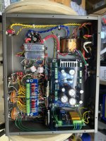
Hello - I have completed the build of my EQ1616D phono and I am getting a single voltage reading that does not match the check sheet (HB gives me 226 vdc instead of 68vdc). I have double checked all connections and solder joints, and I don’t appear to be missing any components. I have checked resistors values as well (you will notice I used different brands than supplied in the kit). I am at a bit of a loss here and any help would be appreciated.
I have checked voltages with wall Vac @119 and using a recent production 5AR4 (GZ34) tube.
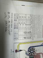
The wire off of the HB test point goes to pin 9 of V3 (then pin 9 V2 and V3 serially). Unless I am wrong this is the heater center tap and used when wiring the filaments (pin 4 and 5) in parallel. So, I tested between pin 9 and pin 4 and got 6.0 vdc and between pin 9 and pin 5 and got 6.0 vdc. This seems correct, but on an elevated DC baseline of 226vdc instead of what the manual says should be 68vdc.
I also measured the equivalent of these at CN11 on the PCB and got the same values 6.0vdc between HC and +Vh (and -Vh).
I followed page 4/22 of the assembly manual (the schematic page). And tested each section between the rectifier 5vac connections to the v3 pin 9 (and 4 and 5) and the numbers seem to be correct.
A) The 5vac secondary (blue wires to rectifier) give 5vac, 12vac secondaries (green wires and purple wires from transformer) give ~13vac at AC2/AC2 and AC3/AC3 connections, respectively.
B) B0+ measures 280vdc (btw the red and black wires) at CN8 on the PCB
C) B1+ measures 226vdc at CN9 on the PCB
So, it appears that my reading at checkpoint HB is the same voltage as B1+.
Any thoughts of what is incorrect or what else I can check?
I have checked voltages with wall Vac @119 and using a recent production 5AR4 (GZ34) tube.
The wire off of the HB test point goes to pin 9 of V3 (then pin 9 V2 and V3 serially). Unless I am wrong this is the heater center tap and used when wiring the filaments (pin 4 and 5) in parallel. So, I tested between pin 9 and pin 4 and got 6.0 vdc and between pin 9 and pin 5 and got 6.0 vdc. This seems correct, but on an elevated DC baseline of 226vdc instead of what the manual says should be 68vdc.
I also measured the equivalent of these at CN11 on the PCB and got the same values 6.0vdc between HC and +Vh (and -Vh).
I followed page 4/22 of the assembly manual (the schematic page). And tested each section between the rectifier 5vac connections to the v3 pin 9 (and 4 and 5) and the numbers seem to be correct.
A) The 5vac secondary (blue wires to rectifier) give 5vac, 12vac secondaries (green wires and purple wires from transformer) give ~13vac at AC2/AC2 and AC3/AC3 connections, respectively.
B) B0+ measures 280vdc (btw the red and black wires) at CN8 on the PCB
C) B1+ measures 226vdc at CN9 on the PCB
So, it appears that my reading at checkpoint HB is the same voltage as B1+.
Any thoughts of what is incorrect or what else I can check?
Attachments
Not really my plan to use it, other than possibly during testing at the end of the build process. However, the metal tube does not fit onto the base. The parts for the rectifier are supplied in the same bag, and the manual shows the tube as being mountable to the base. The tube can fit around the top for maybe a centimetre, but I can't push it down all the way. That's with about as much force as I can apply by hand, and it makes no difference if l try and work back and forth a little. That's why I wondered if I missed something. All the parts and instructions I've dealt with so far have been meticulous.

Hello - I have completed the build of my EQ1616D phono and I am getting a single voltage reading that does not match the check sheet (HB gives me 226 vdc instead of 68vdc). I have double checked all connections and solder joints, and I don’t appear to be missing any components. I have checked resistors values as well (you will notice I used different brands than supplied in the kit). I am at a bit of a loss here and any help would be appreciated.
I have checked voltages with wall Vac @119 and using a recent production 5AR4 (GZ34) tube.
The wire off of the HB test point goes to pin 9 of V3 (then pin 9 V2 and V3 serially). Unless I am wrong this is the heater center tap and used when wiring the filaments (pin 4 and 5) in parallel. So, I tested between pin 9 and pin 4 and got 6.0 vdc and between pin 9 and pin 5 and got 6.0 vdc. This seems correct, but on an elevated DC baseline of 226vdc instead of what the manual says should be 68vdc.
I also measured the equivalent of these at CN11 on the PCB and got the same values 6.0vdc between HC and +Vh (and -Vh).
I followed page 4/22 of the assembly manual (the schematic page). And tested each section between the rectifier 5vac connections to the v3 pin 9 (and 4 and 5) and the numbers seem to be correct.
A) The 5vac secondary (blue wires to rectifier) give 5vac, 12vac secondaries (green wires and purple wires from transformer) give ~13vac at AC2/AC2 and AC3/AC3 connections, respectively.
B) B0+ measures 280vdc (btw the red and black wires) at CN8 on the PCB
C) B1+ measures 226vdc at CN9 on the PCB
So, it appears that my reading at checkpoint HB is the same voltage as B1+.
Any thoughts of what is incorrect or what else I can check?
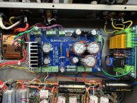
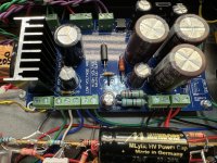
Since the HB voltage is almost equal to the B voltage, one of the following parts that divides the B voltage is suspect.
(1) R105 (68kΩ/1W) is not conductive due to bad solder.
(2) R104 (220kΩ/1W) is shorted due to use wrong resistor ( with a low resistance (2.2kΩ or so) )or solder bridge.
Did you follow the manual:
Use a file to smooth soldered part of the socket pin.
I'm not at the stage of plugging anything into anything yet. The problem is not with the pins: it involves the other side of the base, where the aluminium tube is supposed to be mounted onto it. It doesn't fit over the plastic, and the only thing I can think of is that it would take a lot of filing down, of the tube, the base, or both, to get them to mate. Which doesn't seem right. But with the metal tube I have, jamming it onto the socket by hand is very much not an option.