Many here try to combine the soft start and the slow charge into a primary located resistor with or without a timed delayed bypass.
I don't believe this is possible.
I always recommend a quickly bypassed soft start resistance in the primary.
If the capacitors need a slow charge then I recommend a secondary located resistance with a MUCH longer delayed bypass.
In both of these I accept the correctly selected power NTC resistors are better than fixed power resistors.
But I find this solution is far too expensive in the UK and I use fixed resistors, even though I know that NTCs would be better. I have 8off NTC samples (4 values of resistance/current) with which I can experiment that proves to me that fixed resistors are second best.
But I find this solution is far too expensive in the UK and I use fixed resistors, even though I know that NTCs would be better.
They would appear to cost only a little over £1...
The NSC application note snaa057b is instructive, because it contains actual oscilloscope waveforms of an actual linear power supply during soft-start. Have a look at Figure 5 in particular; it shows the filter capacitor voltage vs time.
Notice that the extra resistance in the transformer primary (the "soft start") only participates for the first 500 milliseconds after switch-on. If the mains frequency is 50Hz and if a full wave bridge rectifier is used, there will be 50 waveform crests during those 500 milliseconds. You will get 50 diode current-pulses during soft start. Fifty! That turns out to be quite a lot.
As I'm sure you've seen in simulation, the frightening aspect of filter-capacitor-charge-up occurs on the first five to ten waveform crests. These are the ones whose diode current-pulses are truly enormous. After about the tenth current pulse (about 100 msec after startup), the current pulses are no longer frighteningly huge. NSC's current limiter prevents these first ten current-pulses from being enormous. And the next ninety pulses thereafter, too.
So NSC has managed to put together a 9-element soft start circuit which quite successfully limits current to both the transformer and to the rectifier/capacitor assembly. They didn't need two separate soft start circuits with wildly different activation times. An ICL thermistor would prolong the startup event over an even longer time than 500 msec , see the GE data sheet. You can form your own opinion about whether this is preferable or not.
By the way, inquisitive readers might enjoy printing Figure 5 at high magnification, then measuring asymptotes, slopes, curvatures, breakpoints, and the like. You may be able to extract the total series resistance of the experimental setup (Mains Rthevenin impedance + xformer wire resistance + xformer core losses + PCB track resistance + Capacitor ESR + diode tangency (dV/dI) + etc).
Last edited:
Following on from those links and SGK's estimate.
Rapid don't sell any CL60, nor near equivalent.
RS seem to only sell small NTCs (no Joules quoted, they state 450mW).
Farnell do CL60 @ £1.83 and one needs two of these for 240Vac. They also do a few 3.1W NTCs but there is not any Joule data although price is lower than CL60.
Ti show 3 paralleled 68r and these are a close equivalent resistance to a pair of series connected CL60.
I've never had any issue ordering from Mouser in the UK. You pay the VAT and they manage their import costs. Shipping is free if you aggregate your orders over the £50 threshold. Their UK-based customer service team is a simple phone call away.
But we digress... I'm still trying to figure out why a CL-80 works when Cmax of 1250uF is rather low...
But we digress... I'm still trying to figure out why a CL-80 works when Cmax of 1250uF is rather low...
Re Ti plot of voltage vs time:
Note the initial slope of voltage during and after the start up.
Note the slope of second stage voltage rise, just after the relay bypasses the fixed resistors.
This indicates a very much higher rate of current flow.
Where is that increased current going?
Is that current charging the smoothing capacitance?
If the 68/3r is replaced by one CL60 @ ~10r, what will the charging current pulse look like?
I don't have the equipment to examine this.
what voltage are they stating?....... I'm still trying to figure out why a CL-80 works when Cmax of 1250uF is rather low...
120Vac, or 240Vac, or 340Vpk?
I had the datasheet open but closed it down.
Got it back up.
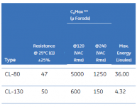
5mF @ 120Vac and 1250uF @ 240Vac
I wonder if the quadrupling of capacitance is always for a halving of voltage? Implying a squared law?
60Vac may be 20mF
and that would be OK for the secondary located CL80 in half a dual polarity supply of +-20mF rising to ~+-90Vdc
But note that a pair of secondary located CL80 limiting the charging currents, will operate very differently from one, or two, CL80 in the primary circuit.
Last edited:
Easier (better?) to look at the max energy that can be stored in the ICL and use the formula for deriving the energy stored in a capacitor to work out the maximum capacitance for the voltage at which the caps are charged.
Energy stored in a capacitor (J) = 1/2CV^2 (where C is expressed in Farads)
Energy stored in a capacitor (J) = 1/2CV^2 (where C is expressed in Farads)
Page 2 of the GE datasheet for Inrush Current Limiters (link) talks about the relationship between {energy stored in the filter capacitor} and {the datasheet rating for max_capacitance @ voltage}
To double-check that you understand the way GE are rating their ICL thermistors, see whether you can calculate the max_capacitance @120VAC rms for the CL-80, knowing only that the CL-80 is rated for 36.0 Joules, max. Does your calculated capacitance agree with the datasheet value? Repeat for the CL-80 max_capacitance @240VAC rms, given that CL-80 is rated 36.0 Joules max. Does your value match the datasheet's value?
Repeat for the CL-130, rated 4.32 Joules max. What's max_cap @ 120VAC rms? What's max_cap @ 240VAC rms? Do you match the datasheet?
Once you're able to replicate GE's calculations, you can now compute max_capacitance @ XYZ volts AC rms, using only the max Joule rating and your understanding of GE's calculation procedure. For any XYZ voltage you choose. Even the transformer secondary voltage.
Attachments
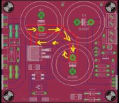
Assume the PCB track resistance is 4 milliohms per inch. Create two schematics showing the two layout options INCLUDING the PCB track resistance.
Do you prefer one schematic over the other, aesthetically?
Run them in LTSPICE. Does one schematic's performance please you more than the other, even by half a percent? If so, why not use the layout that's 0.5% better -- the cost is zero so the (benefit/cost) ratio is infinity.
Do you prefer one schematic over the other, aesthetically?
Run them in LTSPICE. Does one schematic's performance please you more than the other, even by half a percent? If so, why not use the layout that's 0.5% better -- the cost is zero so the (benefit/cost) ratio is infinity.
ok but my question is whether, other than trace length/resistance, are the two circuits functionally the same? I know this is incredibly basic but conceptually I still follow schematics from source to output and worry when the board doesn't follow the "flow" of the schematic. I presume this is a hump I just need to get over but I'm unsure.
Hmm. My cause for nervousness. But.... another example which would seem very analogous: the DIYAudio Universal PSU board. http://files.diyaudio.com/forums/gallery/data/500/medium/PSU18.jpg Schematic is C1->C2-> resistor bank -> C3->C4. Yet C2 is on a spur from C1. The trace doesn't run from C1 to C2 and from C2 to the resistor bank. It's quite similar to my markings in orange. If one thinks in nodal network terms the two are the same (the elements C1, C2 sit on the correct side of the transistor - how they are connected, ignoring trace resistance, is irrelevant) but if your mindset is 'flow' (from C1->C2-> transistor) then they're not. Hence my question, even if it is a stupid one.
One way to experimentally "ignore trace resistance" (or more generally, trace impedance) is to use .PARAMs in LTSPICE. The "LIST" option allows you to run three or five or twenty simulations with different values of the params, and plot all simulation results overlaid on the same output graph. You can step the trace resistance/impedance from high to medium to low to near-zero, and see the effects (if any) upon circuit behavior.
PCB copper trace resistance "calculators" abound on the internet; all you do is input the thickness of your copper layer (in oz/ft2), the width of your trace, and the PCB temperature. Then, presto, they spit out the trace resistance per unit length. It might surprise you to see that one inch of PCB trace has a greater resistance than SGK's MOSFET switch -- but it does. Really.
Copper trace impedance "calculators" are also online, but less numerous. They cover microstrip layouts, stripline layouts, and coplanar waveguide layouts {Wikipedia discusses each of these}, and spit out inductance-per-unit-length, capacitance-per-unit-length, characteristic impedance, propagation velocity, and so forth. If you want to simulate impedance instead of resistance, these can help.
I myself would use the methodology outlined in post #115 to decide between the two layout styles. I might even vary the trace resistance above, and below, the real-world number, just to see whether the difference between the two layouts becomes shockingly huge if we make PCBs traces out of high resistance tungsten (or out of zero resistance superconductors). Maybe LayoutX is vastly superior to LayoutY in one of these what-if scenarios, despite X&Y being nearly-indistinguishable in the copper trace scenario. It's likely I would choose X rather than Y for this very reason. But hey that's just me.
Last edited:
What are the things to beware of regarding installation of a CL-80 or similar? It will obviously get hot. How hot? (order of magnitude) I understand that it presents a high resistance at room temperature, heats with current and as it heats its resistance falls. If I-load falls does the temperature of the NTC thermister fall?
As noted previously, I was planning to potentially have two toroids: one for the 5V and 3.3V power rails and another for the 12V rail. (While I note that the manufacturer I was exploring produces toroidal transformers with a minimum secondary voltage of 10VAC, this is not enough headroom for the 12V power supply.)
Andrew has strongly recommended that I fuse each transformer separately. Ideally I would like the fuse holders to be panel mounted - I have one of these fuse holders already - and located near the (single) IEC inlet. Add in a switch and I guess I have a confluence of wiring there. I'm wondering, therefore, how to physically wire - safely and efficiently - the NTC ICLs. (I assume one is placed in series on each of the Live and Neutral.)
Also, is my mathematics/understanding correct:
Resistance on secondary = Resistance on primary / Turns Ratio Squared
So, for the CL-80 with 47Ohms resistance at 25C and a 10V secondary / 230V primary transformer:
Rs = 47/529 = 88.9mOhms
- Status
- This old topic is closed. If you want to reopen this topic, contact a moderator using the "Report Post" button.
- Home
- Amplifiers
- Power Supplies
- Enough current to turn on 3 mosfets?