But it is very important to find a link between subjective opinions and actual physics. Well, at least that's what I discovered during working flight controls. It's like, when a pilot tells you the control is a bit sluggish, you have to be up to par to feel what he is feeling to be able to come with the right solution.ronc said:I truly hate getting into metaphysics here.
Take anybody in the world who can drive. Give them a Yugo to drive and then let them drive a Porshe 930 turbo to drive. Ask them to define the difference. The difference they describe is subjective. They cant describe the actual physics of the difference. All we (or i) want to do is define the actual physics.
ron
Yeah, but you can empirically test the differences between the 2 cars, and objectively quantify what makes the (subjective) difference between a Porsche 930 vs a Hugo.
We know exactly what the parameters of weight distribution, center of gravity, the mass centroid axis, polar moment of inertia, roll centers, unsprung weight, camber gain of the suspension through bump travel, caster, steering ackerman, shock valving for damping and rebound, tire slip angles etc.... for the 2 cars are.
Science allows us to measure the differences, and understand all those things, and allows us to predict what directions to go in further developing things.
There's nothing subjective about that.
Cheers
Carlp said:
John,
FWIW, I didn't understand your treatment either. You thought it was clear, but I didn't. I asked myself the same question Budp asked you.
Carl
Are you guys reading the same words I am? The only way it could be more clear would be for john to post a picture. I would understand if he chose not to respond further given what he has posted, to include the descriptions.
Re-read the post. It can't be more straight-forward than it is, to whit:
- single ring of "pin stripe" tape, 1/8" wide, 0.0035" thick (height off the baffle)
- A circular pattern 8 1/2" in diameter centered around the driver...chosen because it maximized the effect of diffraction from the tape
- Mic positioned 5 1/2" from driver dust cap on axis
The times listed simply reflect the distances. Any diffraction from the ring is time-delayed due to the geometry of driver AC to ring to mic (total path length as indicated on the impulse responses).
How can it be any simpler? The test was geared to produce the maximum effect (whatever it might be) from the application. Test for an effect, measure that effect.
The key point is that "there aren't any differences due to the diffraction ring". There is essentially no significant alteration to the impulse response due to the ring. If an application of any material anywhere close to the dimensions (height, width) of the enabl application is placed on a baffle (I'll add "or any immobile surface"), it makes essentially no change to the impulse response that passes over it. John's measurements confirm this fact. If that impulse response is not altered, then that same impulse response continues on to whatever other discontinuity exists (a baffle edge, for instance, no matter how near nor how far). Since that impulse response is unaltered, the subsequent diffraction that exists before the application will exist unaltered after the application, because the same impulse energy will encounter the baffle edge. It is without effect in the audible range.
Dave
Originally posted by john k... - Post #135
I don't think anyone here would argure thaty 1" x 1/2" block of what ever material you are using would have an effect. I certainly never would. But I'd would not place that in the catagory of an Enable process, unless by Enable it is meant any adhoc baffle, port, driver treatment... that migh alter something.
But the idea that a 0.0035" tall application of paint to anything (Baffle, port, cone, dome or a tweeter) will have any effect at all on the surface wave in the audible frequency range,that is in any way audible is rediculous. Let's put this nonsense about BLs etc to rest once and for all. Applied to a driver it is all the effect of the altered cone properties/vibration and resulting alteration in frequency response, and perhaps, changes in directivity at higher frequencies.
G'day john k (and others),
Just to clarify what I'm refering to as 'EnABL' when talking about baffles and ports:
- block material is either PVC duct tape or aluminium foil backed with double sided tape
- paint is not used as a block material
- block size is calculated, not ad hoc - which I have outlined here.
- EnABL pattern size is directly related to the block size
- The EnABL pattern is applied as a straight pattern either along baffles edges or around the inside circumference of a port.
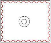
I have attached a pic which roughly represents what EnABL would look like on your test baffle - note that the block sizes and baffle are NOT to scale.
I'm happy to adopt an alternative description if that will make things clearer for everyone.
Suggestions?
Cheers,
Alex
Attachments
Are you guys reading the same words I am? The only way it could be more clear would be for john to post a picture.
A mental picture is what I want. John's post suggested a solid ring of pinstripe tape. But I figured that couldn't be b/c it's so far from what the enable pattern is. So forgive me for assuming I must have misunderstood what he did. If what he did is, in fact, a solid ring of pinstripe tape, then I did read his post right, but from a SCIENTIFIC, OBJECTIVE and TECHNICAL point of view, what he did is irrelevant and belongs on the other thread...

Carl
Re: Re: Re: No one is grasping the import of john's posts
The ones i use have an additional level of pre-treatment and the measures i have are of stock vrs pre-treat+ EnABL. Al Wooley has samples of at least one instance each of stock, pre-treatment only, EnABL only and pre-treat _ EnABL. He will be testing those before he gets the TBs (i think). He uses them with XOs at 125. 700, and 2k in different speakers.
dave
dlr said:I would be very interested in before/after measurements raw, then the same with a crossover in place. Got any to show?
The ones i use have an additional level of pre-treatment and the measures i have are of stock vrs pre-treat+ EnABL. Al Wooley has samples of at least one instance each of stock, pre-treatment only, EnABL only and pre-treat _ EnABL. He will be testing those before he gets the TBs (i think). He uses them with XOs at 125. 700, and 2k in different speakers.
dave
Carlp said:
A mental picture is what I want. John's post suggested a solid ring of pinstripe tape. But I figured that couldn't be b/c it's so far from what the enable pattern is. So forgive me for assuming I must have misunderstood what he did. If what he did is, in fact, a solid ring of pinstripe tape, then I did read his post right, but from a SCIENTIFIC, OBJECTIVE and TECHNICAL point of view, what he did is irrelevant and belongs on the other thread...
Carl
You couldn't be more wrong.
This should not be confusing at all and is not to me. What he did was maximize whatever effect a material of the dimensions of the recommended enabl application would have. Maximal effect, by placing it in a circle, meaning all points equidistant. I've documented the same situation for diffraction at my site for rings vs. block patterns for an actual effective treatment for diffraction on a baffle. Circles are known to provide the most impact on diffraction, ever since the pioneering research by Olson back in 1969 (see "Direct radiator loudspeaker enclosures", Journal of the Audio Engineering Society, 17, No1, 22-29). John's results show unequivocally that ANY pattern of dimensions on the order of the enabl application will not have any significant effect on an immobile surface in the audible range since it has no significant impact for the worst case scenario, a full circle.
It can't get any clearer than that.
Dave
Anyone, please offer your analysis of John's posted data
I fully expect there to be measurable differences between any treated vs. untreated driver. Anything with a pre-treatment+enabl for which there is no measurement just prior to enabl treatment is of no use whatsoever. It also cannot be a comparison of different drivers (i.e. one untreated and another one treated). To be valid at all, it has to be the same driver measured before and after, both without a crossover and with a crossover, though it would be acceptable to take the raw measurement and post results of CAD simulation of the crossover since distortion measurements are not included (sadly). Since the claim is that no design changes are needed, a single crossover would work, but personally I would never leave a crossover unchanged if I altered the driver response in some significant way.
To ask again, are you, or anyone else for that matter, going to provide any input (as in analysis) whatsoever of John's posted measurements relating to ambient air pressure testing of a driver? Anyone at all? The implication is clear (to me at least) and significant to the enabl mechanism debate. Why will no one step up to the plate and offer their interpretation?
Bud professed great interest in objective data. Well, there it is with no response whatsoever, not even probing questions other than one by soong (with no followup), for this one:
So how about it? Anyone, anyone at all have anything to offer? What is the fundamental consideration?
Dave
planet10 said:
The ones i use have an additional level of pre-treatment and the measures i have are of stock vrs pre-treat+ EnABL. Al Wooley has samples of at least one instance each of stock, pre-treatment only, EnABL only and pre-treat _ EnABL. He will be testing those before he gets the TBs (i think). He uses them with XOs at 125. 700, and 2k in different speakers.
dave
I fully expect there to be measurable differences between any treated vs. untreated driver. Anything with a pre-treatment+enabl for which there is no measurement just prior to enabl treatment is of no use whatsoever. It also cannot be a comparison of different drivers (i.e. one untreated and another one treated). To be valid at all, it has to be the same driver measured before and after, both without a crossover and with a crossover, though it would be acceptable to take the raw measurement and post results of CAD simulation of the crossover since distortion measurements are not included (sadly). Since the claim is that no design changes are needed, a single crossover would work, but personally I would never leave a crossover unchanged if I altered the driver response in some significant way.
To ask again, are you, or anyone else for that matter, going to provide any input (as in analysis) whatsoever of John's posted measurements relating to ambient air pressure testing of a driver? Anyone at all? The implication is clear (to me at least) and significant to the enabl mechanism debate. Why will no one step up to the plate and offer their interpretation?
Bud professed great interest in objective data. Well, there it is with no response whatsoever, not even probing questions other than one by soong (with no followup), for this one:
An externally hosted image should be here but it was not working when we last tested it.
So how about it? Anyone, anyone at all have anything to offer? What is the fundamental consideration?
Dave
CarlP,
John does have the proper tape width for that diameter of outer pattern ring. I have attached a simple dimensioned drawing to show this.
I am assuming he is just condensing the pattern into a solid for simplicity. On the other hand I have no idea from this what effect the offsets might actually have. It is good to have a baseline though, so when we get to looking at Alex's tape patterns we do have one data point.
I will again say that my expectation for a ring here, around a driver or even two drivers would be a very slight change in mix height, and that would be pretty debatable. In conjunction with an outer pattern there may be some more usefulness, but I haven't done this combination in a number of years, so at some point I must have decided it was not worth the time to apply.
Attachments
Re: Anyone, please offer your analysis of John's posted data
They are of great use... once i'm done they are a very nice driver...
8 of the drivers Al has were measured before, now they are going back for measures after pre-treatment and some will get fully treated and back again.
As i have been sayiong for some time, and as John'd data helps emphasis, any data collected that are not done at the same temperature, humidity and atmospheric pressure will have a significant error margin.
dave
dlr said:Anything with a pre-treatment+enabl for which there is no measurement just prior to enabl treatment is of no use whatsoever.
They are of great use... once i'm done they are a very nice driver...
8 of the drivers Al has were measured before, now they are going back for measures after pre-treatment and some will get fully treated and back again.
As i have been sayiong for some time, and as John'd data helps emphasis, any data collected that are not done at the same temperature, humidity and atmospheric pressure will have a significant error margin.
dave
I have to agree with drl here. Some of you must be pretty thick if you can not understand the tests I did. So I will take the time to explain what was tested and why. (Excuse me, but like I said, I'm tired of being polite).
First,why? When looking at any scientific problem with several features present one of the first things to try and do is to get an understanding of the way various components can enter the problem. With cone modification there are several things including 1) how wave propagates in the cone, 2) how waves are launched from the cone, 3) how the application of the pattern alters cone vibration and 4) how application of the pattern might alter wave propagation as it passes over the applied patches.
The tests I performed were done to examine item 4 by isolating the effect of the patch on wave propagation over it. It is not a test of enable. It is a test of how a surface disruption the height and width of a typical enable patch applied to a driver cone will interact with an acoustic wave as the wave passes over the disruption. Being applied to the baffle rather than the cone, changes due to items 1-3 listed above are eliminated. The sound radiated by the source remains unaltered. So the measured data with and without the obstruction reflect only the effect of that obstructions the wave passes.
In the first tests I used a solid circular ring. Since the distance form the acoustic center of the sources to the ring is constant for all circumferential positions when the mic in on axis this will result in maximizing any disturbance cause by the ring because the time from source to ring to mic is constant. I noted the position where any difference due to the ring should first appear in the time plots. Furthermore, I used a large baffle so that the edge diffraction would occur much later in time and therefore would not contaminate the result a short time after the wave initially passed the obstacle, as it would if the ring were close to a baffle edge. The data showed no effect due to the obstacle at all, down to about -60dB below the peak magnitude of the impulse.
Soongc asked about noise. For the levels used in the tests the noise floor was about -70dB below the impulse peak. So it is possible that even the insignificant differences observed are nothing more than noise.
The second test I did was actually a better test. This is because the first test looked at the direct impulse with any perturbation from the ring being added to it, delayed in time. In the second test, where the mic was flush mounted in the baffle just outside the ring, the data represents only the surface wave and yields a direct measure of any disruption of the wave by the obstacle. Even in this more sensitive test it was shown that such an obstacle is acoustic invisible. There is no change to any part of the impulse, initial rise or late time response. You can reach this conclusion for yourself by examining the data.
So, this is not a test of enable. Rather if is a test of one component of enable performed to isolate the effect of this component on the propagation of an acoustic wave as it passes over it.
I would not be surprised if someone tried to make an argument for the fact that this is not an enable pattern or that it is not a double ring. My response to that is just as I have said before. An acoustic wave doesn't see a disruption until it arrive at the disruption. If it passes the first disruption unaltered it encounters the next disruption in the same state as it would if the first disruption were not present. However, for the sake of completeness I will probably, at some time, make true enable rings on the baffle and retest.
Re: Re: Anyone, please offer your analysis of John's posted data
I had not intended to comment on the sound of the driver, only on the test methodology. They may indeed be a very nice driver afterwards.
There will be a difference, yes, but I'd be surprised to see a significant error margin for most typical in-room conditions. A quick search found this (Wikipedia):
"In fact, assuming an ideal gas, the speed of sound c depends on temperature only, not on the pressure or density (since these change in lockstep for a given temperature and cancel out). Air is almost an ideal gas."
So the change will be almost exclusively related to temperature variations, not pressure nor density. That is, unless the driver is in a closed box, perfectly sealed (as in air-tight) and the air pressure is significantly different. There would be some alteration of the Fc in this case. If the room temperature changed, there would be some change in measured response as well, I haven't tried to find out how that will vary. But again, if it's in-room in both places, I would not expect any significant change to the measured response for most situations. Even going from sea level to Denver would not significantly change the measured response other than for the perfect closed box case.
Dave
planet10 said:
They are of great use... once i'm done they are a very nice driver...
I had not intended to comment on the sound of the driver, only on the test methodology. They may indeed be a very nice driver afterwards.
As i have been sayiong for some time, and as John'd data helps emphasis, any data collected that are not done at the same temperature, humidity and atmospheric pressure will have a significant error margin.
dave
There will be a difference, yes, but I'd be surprised to see a significant error margin for most typical in-room conditions. A quick search found this (Wikipedia):
"In fact, assuming an ideal gas, the speed of sound c depends on temperature only, not on the pressure or density (since these change in lockstep for a given temperature and cancel out). Air is almost an ideal gas."
So the change will be almost exclusively related to temperature variations, not pressure nor density. That is, unless the driver is in a closed box, perfectly sealed (as in air-tight) and the air pressure is significantly different. There would be some alteration of the Fc in this case. If the room temperature changed, there would be some change in measured response as well, I haven't tried to find out how that will vary. But again, if it's in-room in both places, I would not expect any significant change to the measured response for most situations. Even going from sea level to Denver would not significantly change the measured response other than for the perfect closed box case.
Dave
You couldn't be more wrong.
Wrong that I was confused? Oh, gee, sorry dlr, I didn't realize that I actually understood John K.
The use of a solid ring for the test is relevant if the theory being tested was correct. But what if it isn't? Then the use of a solid ring is no more correct than using holes drilled in the cone or baffle since that is so very different than the block pattern. I maintain my position given what I understood on reading his post (hmmm, is that an opinion or fact?).
Now, John's last post explains things and if I'd had that explanation before, I would have understood. This constant heckling of people who don't immediately understand what is being discussed seems kinda pointless to me. I was simply responding the the accusation that Bud was somehow dumb for being confused - obviously he wasn't alone. I am not stupid.
Please just respond to my confusion with a pleasant explanation or leave it alone. Unless it makes you feel good, in which case I don't see how it belongs on this objective thread.
Carl
Re: Anyone, please offer your analysis of John's posted data
Maybe you can shed some light on what you think we all don't know?
Air load damping is very basic, I don't know what you expect from these charts.dlr said:
I fully expect there to be measurable differences between any treated vs. untreated driver. Anything with a pre-treatment+enabl for which there is no measurement just prior to enabl treatment is of no use whatsoever. It also cannot be a comparison of different drivers (i.e. one untreated and another one treated). To be valid at all, it has to be the same driver measured before and after, both without a crossover and with a crossover, though it would be acceptable to take the raw measurement and post results of CAD simulation of the crossover since distortion measurements are not included (sadly). Since the claim is that no design changes are needed, a single crossover would work, but personally I would never leave a crossover unchanged if I altered the driver response in some significant way.
To ask again, are you, or anyone else for that matter, going to provide any input (as in analysis) whatsoever of John's posted measurements relating to ambient air pressure testing of a driver? Anyone at all? The implication is clear (to me at least) and significant to the enabl mechanism debate. Why will no one step up to the plate and offer their interpretation?
Bud professed great interest in objective data. Well, there it is with no response whatsoever, not even probing questions other than one by soong (with no followup), for this one:
An externally hosted image should be here but it was not working when we last tested it.
So how about it? Anyone, anyone at all have anything to offer? What is the fundamental consideration?
Dave
Maybe you can shed some light on what you think we all don't know?Jeepers, much has been posted since yesterday - 60 posts will take some catching-up !
Hi Bud,
Your 'bottom note' observations in Post#109 relating to bass viola, piano, sousaphone, bass drum 'induced ripples' seem like aspects I have heard due to the low frequency response of amplifiers failing to control amplifier /crossover /driver /cabinet interaction and thus causing modulation of an on-going waveform, which otherwise might be curable by improving the amplifier.
However if you have observed EnABL alone effecting improvement, then I cannot challenge this.
Or maybe the problem being cured related to something else.
Hi John K,
More 'show and tell in Post#111. Excellent.
I want to come back to this, but first I must read everybody else's contributions to date.
____________________________________________________
(( and then I must wade through more pointedly unnecessary posturing and deconstruction with one poster actively seeking comment on 'the show and tell' before he will grant his opinion upon that interpretation. Yeough! ))
____________________________________________________
John, re your baffle strip test in Post#123. Excellent.
I 'guess' you knew this would show nothing but felt it worth investigating to prove same anyway.
However, I do not see how you can then go on to objectively claim in Post#127;-
>> They (acoustic waves) don't see a change in a surface (enable patch or baffle edge) until they get there. So if a ring about the dimensions of an enable patch is place away from the baffle edge and has no effect was so ever (to -60dB or more) on the resulting impulse response, thus no effect on the wave propagation, then it won't have an effect if placed nearer the edge either.<<
and then write;-
>> No need to discuss it further. <<
Would I not be correct in stating that the raised circular strip had no effect upon a single impulse event because no significant transient /steady state velocity /pressure gradient arose at that point on the baffle ?
So how can you attempt to claim the same must be said for EnABL at cone centres, cone edges and baffle edges? This claim does not have an objective foundation.
____________________________________________________
It would be better if everyone here could feel free to discuss
their 'understanding' of what is, or is not, happening, so that everyone might feel free to contribute without arrogant attempts to make to seem like 'inadequately educated students' (from comment in the earlier thread).
____________________________________________________
John K, in Post#144, you then wrote;-
>> "Let me tell you how it's doing to be." <<
Words always say so much about their writer !
Obviously it is going to take me more time than I have available to catch up on the genuinely subjective content, so back later.
Cheers ........... Graham.
basic science
PV=nRT
jeez, some of us learned this in high school physics... for those who've forgotten...
http://en.wikipedia.org/wiki/Ideal_gas_law
rather than challenge the validity of Dave (dlr)'s or John K.'s work wrt diffraction (or not), John K's work on added mass, etc. without a shred of supporting contradictory data, just seemingly random "pot shots" at supposed flaws in reasoning from fundamental concepts that ought to be evident, can we move on to acceptance of what at least IS NOT happening here? As in, no bl causation, no diffraction causation...
There seems to be a double standard running here that the "objectivists", "sceptics", whatever are held to strict interpretations and not allowed to draw conclusions beyond literal interpretations, often taken out of context, of data and/or statements made to support empirical observations.
OTOH, the "subjectivists", "believers", whatever are allowed, in this thread and elsewhere, to make sweeping generalizations using technobabble often based on supposition only, with weak or non existent "data" used purportedly to support "the cause".
give it a rest...
John L.
Carlp said:
Wrong that I was confused? Oh, gee, sorry dlr, I didn't realize that I actually understood John K.
The use of a solid ring for the test is relevant if the theory being tested was correct. But what if it isn't? Then the use of a solid ring is no more correct than using holes drilled in the cone or baffle since that is so very different than the block pattern. I maintain my position given what I understood on reading his post (hmmm, is that an opinion or fact?).
Now, John's last post explains things and if I'd had that explanation before, I would have understood. This constant heckling of people who don't immediately understand what is being discussed seems kinda pointless to me. I was simply responding the the accusation that Bud was somehow dumb for being confused - obviously he wasn't alone. I am not stupid.
Please just respond to my confusion with a pleasant explanation or leave it alone. Unless it makes you feel good, in which case I don't see how it belongs on this objective thread.
Carl
Here is the last line from your post, with caps yours:
If what he did is, in fact, a solid ring of pinstripe tape, then I did read his post right, but from a SCIENTIFIC, OBJECTIVE and TECHNICAL point of view, what he did is irrelevant and belongs on the other thread...
I stand by my statement. You could not be have been more wrong on your emphasized point. You were unequivocal in your statement, in all caps. Maybe I should have indicated this directly, but since you put in the caps to emphasize your point, I replied to that final point.
As to pleasant or not, I stated directly what I thought, that you were wrong. I was not trying to be unpleasant, just direct. It did seem to me that your all-caps direct statement with which I strongly disagreed merited direct response. I'm sorry if you take that as unpleasant. And I did say that it should not be confusing.
Maybe it's some miscommunication on both sides.
Dave
I do recall some sort of ring to pre-warp the baffle diffraction effects was patented, and probably it was a Manger patent. I'm sure rings like these do have effect. But again, like any pattern, there is no cure all formula.
Don't know if it's of any value for discussion or not.
Don't know if it's of any value for discussion or not.
Attachments
- Status
- This old topic is closed. If you want to reopen this topic, contact a moderator using the "Report Post" button.
- Home
- Loudspeakers
- Multi-Way
- EnABL - Technical discussion