The lower the emitter resistor the lower the crossover distortion, once it is set to optimal bias.
Does that equate to:
no emitter resistor is best for minimising crossover distortion?
I suspect not.
Even D.Self, having told us that low values are better than higher values, does not go further and demonstrate the effect of very low or zero-ohms emitter resistors.
Does that equate to:
no emitter resistor is best for minimising crossover distortion?
I suspect not.
Even D.Self, having told us that low values are better than higher values, does not go further and demonstrate the effect of very low or zero-ohms emitter resistors.
Optimal bias depends on the emitter resistor, for most output topologies. For complementary pairs the right resistor value is definitely not zero, unless the output runs in Class A.
The general rule is that at quiescent current the transconductance of one side of the output stage should equal the inverse of the emitter resistor value. As you can't have infinite transconductance you should not have zero resistor value.
The general rule is that at quiescent current the transconductance of one side of the output stage should equal the inverse of the emitter resistor value. As you can't have infinite transconductance you should not have zero resistor value.
Member
Joined 2009
Paid Member
As the intrinsic resistance depends on current you would be chasing your own tail.
There will be a small fixed resistance in a power transistor, but as that is likely to show wide sample variation it is not a basis for good design. There is a reason why designs usually include an emtter resistor - it is not because the designer lacks imagination but because he understands circuits.
There will be a small fixed resistance in a power transistor, but as that is likely to show wide sample variation it is not a basis for good design. There is a reason why designs usually include an emtter resistor - it is not because the designer lacks imagination but because he understands circuits.
@ Bigun
Only $69,995/pair
The only JP Patent with that # i found is this
Not TB ? If anyone can locate the patent, please post the link
**********
Emitter resistors can & have been be eliminated in amps before now. But "usually" with just one output pair !
Have a look at this post:
http://www.diyaudio.com/forums/solid-state/194361-list-best-sounding-amplifiers-22.html#post2878850
It seems that TB uses "long" cables to connect the emitters to the output binding post.
The patent can be found here: Patent & Utility Model Gazette DB
Type B in Kind code field. Type 4284102 in number field
and press search
Attachments
Last edited:
Member
Joined 2009
Paid Member
hello  , I am confused
 that some of the so called emitter resistors is actually connected to the collector of the output transistor in many of the quasi complementary amp designs. What is the use of this resistor connected to the collector? What is the advantage of this resistor placed at the collector over emitter, or vice versa? Please somebody enlighten me.
The below graph are excepted from John. L. Hood and D. Self's books.
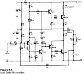
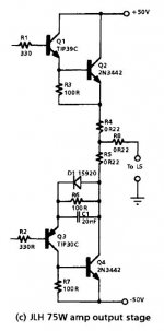
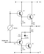
 , I am confused
The below graph are excepted from John. L. Hood and D. Self's books.


leak delta 70 has omitted the emitter resistor from Q6. This will have an effect on the performance of the stage, probably for the worse.
The J:H 75W has omitted both emitter resistors. This can reduce distortion at the expense of increased risk to thermal stability. this could be very good with the correct size of heatsink.
The un-named sch has omitted the emitter resistor from Q4. Same as the Leak, will affect performance.
Now consider the driver pair.
The Leak has an emitter resistor and Q5 on Q3, but Q4 has neither. The loading on the two emitters is very different. This will affect performance, again probably for the worse.
The JLH has Q1 with R3 and Q2 on the emitter. Q3 has D1+R5+C1 on the emitter these extra components are an attempt to load both drivers with the same impedance.
D1 is the Baxandall diode. C1 is the JLH capacitor. R5 is from Shaw if I remember correctly. Three stages of improvement to the quasi comp stage to bring performance upto and some would say exceed a complementary output stage for performance.
The un-named has both drivers with R1/R2 and D1 to mimic the transistor Q4. It is to the Baxandall style. Probably pretty good for driver loading.
Read up Shaw, Baxandall and JLH modifications to quasi complementary output stages.
Considering ONLY the driver+output as a stage, I would expect the Leak performance to be very different from the JLH. It may even be audible, or very audible.
The un-named may come in between for performance and sound quality.
BTW,
the Shaw+Baxandall+JLH modifications are probably at the best of all the quasi output stages when set up correctly. That means the right diode, the right capacitor, the right resistor and the right currents.
Last edited:
The 'emitter' resistor provides local feedback, to either the output pair or the driver pair. For a Darlington output it goes in the emitter of either or both. For a complementary feedback pair it provides feedback to the emitter of the driver.jazzclassics said:I am confused that some of the so called emitter resistors is actually connected to the collector of the output transistor in many of the quasi complementary amp designs. What is the use of this resistor connected to the collector? What is the advantage of this resistor placed at the collector over emitter, or vice versa? Please somebody enlighten me.
The resistor senses the output current and sends a feedback voltage to the driver. It is often still called the 'emitter' resistor even when it is in the collector circuit, as it still provides essentially the same function.
Emitter Resistor in Quasi Complementary Output Stage
Andy,Thank you for your reply.
The unnamed graph is excepted from Chapter6 of D. Self's Audio Power Amplifier Design Handbook 5th edition. Some designs have the R1 in series with Re1, others do not. Any idea what is the difference and which one is better?
The below graph is excepted from Leach's website. Any idea what is the advantage to make the Re like this?
The Leach Amp - Output Stage
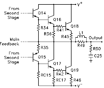
leak delta 70 has omitted the emitter resistor from Q6. This will have an effect on the performance of the stage, probably for the worse.
The J:H 75W has omitted both emitter resistors. This can reduce distortion at the expense of increased risk to thermal stability. this could be very good with the correct size of heatsink.
The un-named sch has omitted the emitter resistor from Q4. Same as the Leak, will affect performance.
Now consider the driver pair.
The Leak has an emitter resistor and Q5 on Q3, but Q4 has neither. The loading on the two emitters is very different. This will affect performance, again probably for the worse.
The JLH has Q1 with R3 and Q2 on the emitter. Q3 has D1+R5+C1 on the emitter these extra components are an attempt to load both drivers with the same impedance.
D1 is the Baxandall diode. C1 is the JLH capacitor. R5 is from Shaw if I remember correctly. Three stages of improvement to the quasi comp stage to bring performance upto and some would say exceed a complementary output stage for performance.
The un-named has both drivers with R1/R2 and D1 to mimic the transistor Q4. It is to the Baxandall style. Probably pretty good for driver loading.
Read up Shaw, Baxandall and JLH modifications to quasi complementary output stages.
Considering ONLY the driver+output as a stage, I would expect the Leak performance to be very different from the JLH. It may even be audible, or very audible.
The un-named may come in between for performance and sound quality.
BTW,
the Shaw+Baxandall+JLH modifications are probably at the best of all the quasi output stages when set up correctly. That means the right diode, the right capacitor, the right resistor and the right currents.
Andy,Thank you for your reply.
The unnamed graph is excepted from Chapter6 of D. Self's Audio Power Amplifier Design Handbook 5th edition. Some designs have the R1 in series with Re1, others do not. Any idea what is the difference and which one is better?
The below graph is excepted from Leach's website. Any idea what is the advantage to make the Re like this?
The Leach Amp - Output Stage

The 'emitter' resistor provides local feedback, to either the output pair or the driver pair. For a Darlington output it goes in the emitter of either or both. For a complementary feedback pair it provides feedback to the emitter of the driver.
The resistor senses the output current and sends a feedback voltage to the driver. It is often still called the 'emitter' resistor even when it is in the collector circuit, as it still provides essentially the same function.
Hi DF96,
Thank you very much
- Status
- This old topic is closed. If you want to reopen this topic, contact a moderator using the "Report Post" button.
- Home
- Amplifiers
- Solid State
- Emitter resistor at output stage transistor.

