Electrocompaniet 25 Watt class A amplifier (The Two Channel Audio Power Amplifier)
HOW TO SETUP THE BIAS AND NULL THE DC OFFSET
Set digital multimeter to 2V DC.
BIAS SETUP
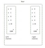
Connect the common meter lead (black)to the RED speaker terminal.
Measure the voltage on test point 'A' and adjust the 1K pot to give a reading of 0.45V.
Check test pins 'B','C' & 'D', if any test point show more than 0.5V reduce the voltage on that test point to 0.5V by adjusting the 1K pot.
NULL THE DC OFFSET
Connect the common meter lead (black) to the RED speaker terminal.
Connect the other meter lead (red) to the BLACK speaker terminal.
Adjust the 220R pot to give a reading of 0V.
LEAVE THE AMP POWER UP
After 1 hour re-check the bias.
Connect the common meter lead (black)to the RED speaker terminal.
Measure the voltage on test point 'A' and adjust the 1K pot to give a reading of 0.4V.
Check test pins 'B','C' & 'D', if any test point show less than 0.4V adjust the 1K pot until it reads 0.4V.
Sharif.
HOW TO SETUP THE BIAS AND NULL THE DC OFFSET
Set digital multimeter to 2V DC.
BIAS SETUP
Connect the common meter lead (black)to the RED speaker terminal.
Measure the voltage on test point 'A' and adjust the 1K pot to give a reading of 0.45V.
Check test pins 'B','C' & 'D', if any test point show more than 0.5V reduce the voltage on that test point to 0.5V by adjusting the 1K pot.
NULL THE DC OFFSET
Connect the common meter lead (black) to the RED speaker terminal.
Connect the other meter lead (red) to the BLACK speaker terminal.
Adjust the 220R pot to give a reading of 0V.
LEAVE THE AMP POWER UP
After 1 hour re-check the bias.
Connect the common meter lead (black)to the RED speaker terminal.
Measure the voltage on test point 'A' and adjust the 1K pot to give a reading of 0.4V.
Check test pins 'B','C' & 'D', if any test point show less than 0.4V adjust the 1K pot until it reads 0.4V.
Sharif.
Attachments
Last edited:
")
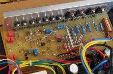
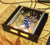
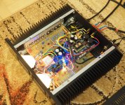
I decided to make a copy of this amplifier
in red (schematic diagram) used substitutes.
Power Supplies : fifimediy SMPS300R
in red (schematic diagram) used substitutes.
Power Supplies : fifimediy SMPS300R
Attachments
-
 01.jpg.5e1894db91e9989aad9a272929455801.jpg115.1 KB · Views: 591
 -
 Bez nazwy 1.jpg863.3 KB · Views: 413
 -
 Bez nazwy 2.jpg727.6 KB · Views: 401
 -
 Bez nazwy 3.jpg744.6 KB · Views: 457
 -
 Bez nazwy 4.jpg969.5 KB · Views: 350
 -
 PCB.jpg.7fc5543512240caaaf89c5656966cd7c.jpg118.2 KB · Views: 500
 -
 sch2.gif17.2 KB · Views: 559
schematic in post #3 (one of the AW-100 versions) under
Electrocompaniet Ampliwire 100 (AW 100 AW100) different Versions
shows an other topology consist of a transconductance (VC- resp. OTA-) amp for the input stage and a normal operational amplifier stage working as inverted amplifier.
Actually is the input resistor for the inverted mode replaced by an OTA stage.
Otala amplifier power supply
Hi there...for some time I looking on idea to build amplifier based on original article regarding Otala amp (IEEE from 1973) but I do not have any information how to build PSU for that amplifier. For output stage is noted voltage of bipolar 24V and for input and driver is bipolar 30V. My plan is to make regulated PSU for input (bipolar 30V) and for output stage I will use common circuit: transformer- bridge rectifier-cap 2x8800uF/100V. My greatest question is what is needed transformer secondary voltage for bipolar 24V part of PSU? Any info will be helpfull...
With best regards from Croatia
Try applying basic math of dividing by 0.707 for AC as 20 Volts AC rectified is 28.30 as it is multipled by 1.414.
So 50volts DC would need a transformer of 35.5 volts AC as you divide by .707, come on this is first year stuff???
Also remember this is "off load" so you may lose a couple of volts on load so use a voltage regulator to get the final required voltage.
So 50volts DC would need a transformer of 35.5 volts AC as you divide by .707, come on this is first year stuff???
Also remember this is "off load" so you may lose a couple of volts on load so use a voltage regulator to get the final required voltage.
Hi, in your new amp,did you bias the toshiba transistors to the same level as the original ones - 400mV? I'm thinking they may be a good alternative for the BD203/4 I have presently.I decided to make a copy of this amplifier
in red (schematic diagram) used substitutes.
Power Supplies : fifimediy SMPS300R
Many Thanks
Joe
Hej, lets see if there´s still life in this thread. I have some wonderings about the feed foreward resistor R43 (0,1ohm) that is added in later schematics of the "two channel amp". The chematics is not completly clear on how this resistor should be connected in the cirquit. As it was in my amp the PSU:s ground 0 was connected to the main amp boards ground terminal through this resistor and then from the same resistors "input, seen from the PSU:s side) to the speaker (-) terminal. This is the connection that I´ve also i´ve seen in other "two channel amp" but this does not make sense to me ieven if the amplifier would "work" but it should not create the small feed foreward effect as it was intended to. To get this feed forward effect one should take the ground on the main board directly to the speaker (-)terminal while the 0,1 ohm resistor (from each channel) goes directly to ground 0 on the PSU board right?,...wrong?? Hope this is understandable and I hope someone of you has an answer for me.?
Best regads to you all.
/L-B
Best regads to you all.
/L-B
Hi legarem!
and thanks for the schematics! I´ve seen this before on a site where Terje Sandström(at EC) losly commented the faint sketches on the drawing they did on an early stage in their developments of the amp. About the feed forward resistor he said, I get back to this later but he never did. At the output one can see a faint voltage divider drawn in and a 0,1 ohm connected to ground, so far so good but then there´s a resistor (with no value) drawn straight into the original voltage divider on the scheme and that is where it starts to get a bit confusing. I think that this resistor, not the 0,1ohm one, should be connected to the mainboard common ground terminal to achieve the claimed feed-forward. The value of THIS resistor should not be too critical, maybe 2 ohms or so. Sure I can test this out myself but would be easier if someone could slip me the answer to how Electrocompaniet did it. I know for sure that they did as Terje S. confirmed that they did into their later production of the amp. The feed forward trick was also used by Threshold that started with their 400A model. Thit tightened up the lowest end of the spectrum without having the biggest power supply bank reserv and especially in a class A amp where all reservs only goes to keep the ripple down. Nuff said for now and thanks again for just this schematic! It did some re-lightning for me how they must have done it and it made me look through the lines some more.
Cheers!🍺
- Home
- Amplifiers
- Solid State
- Electrocompaniet original 25 W needs help