Thank you for your reply I agree with what you have said.
I had myself thought about the noise along the power tracks I will now revise the layout.
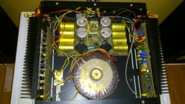
The layout is almost identical to my original board except the revised board is now double side and the track have been increased, also I have changed over the axial capacitors to radial ones.
The connections to the bottom left and right corners of the psu board are the power supply protection circuit that are fed from the emitters of the amplifiers output transistors the top right hand corner is a bistable that feed the relay to break the supply rails.
I had myself thought about the noise along the power tracks I will now revise the layout.
The layout is almost identical to my original board except the revised board is now double side and the track have been increased, also I have changed over the axial capacitors to radial ones.
The connections to the bottom left and right corners of the psu board are the power supply protection circuit that are fed from the emitters of the amplifiers output transistors the top right hand corner is a bistable that feed the relay to break the supply rails.
I am not sure what happened to the link to the web site where the pics of the amps are but it seems to have gone astray. It is here again if anyone wants to download any of the info which is there. If it goes off again, just mail me.
I appreciate the encouragement I have received here concerning the revival of my amps but I really do not have the know-how to do what needs to be done, especially if it involves, as I suspect, new pcbs. So if anyone can suggest someone who really knows what they are doing with these amps I would love to come to some arrangement. Not in the spirit of diyaudio I know but life is short...
Drew?s Hi Fi INFO
Hi Drew
The symptoms you describe are consistent with something that has run too hot all its life and is now getting a bit past it.")
The loud pops and massive DC offsets are caused by some component that has an intermittent connection. It either goes open or short, and throws the whole circuit out of balance.
The usual kinds of loose connections can be "cured" by whacking the unit (I'm sure you've tried this ) but I've seen transistors that go open circuit when they get hot, and these don't respond to hitting, which is one way of identifying them. Last one I saw was in a Mission Cyrus something or other. As far as I know it's caused by the transistor running too hot for a long period of time.
I expect most of the components in the amps will have been made somewhat unreliable by heat, as well as the PCBs like another poster suggested. From the photos you posted, the innards look a bit brown and crispy. A really good repair job would be a rebuild from scratch with new components, which isn't that far off just installing the Velleman amp boards.
I'm based in Glasgow and design industrial electronics for a living, but I design power amps and restore old hi-fi gear for fun. If you are completely stuck, you could always bring one of the things down here.
The symptoms you describe are consistent with something that has run too hot all its life and is now getting a bit past it.
The loud pops and massive DC offsets are caused by some component that has an intermittent connection. It either goes open or short, and throws the whole circuit out of balance.
The usual kinds of loose connections can be "cured" by whacking the unit (I'm sure you've tried this
) but I've seen transistors that go open circuit when they get hot, and these don't respond to hitting, which is one way of identifying them. Last one I saw was in a Mission Cyrus something or other. As far as I know it's caused by the transistor running too hot for a long period of time.I expect most of the components in the amps will have been made somewhat unreliable by heat, as well as the PCBs like another poster suggested. From the photos you posted, the innards look a bit brown and crispy. A really good repair job would be a rebuild from scratch with new components, which isn't that far off just installing the Velleman amp boards.
I'm based in Glasgow and design industrial electronics for a living, but I design power amps and restore old hi-fi gear for fun. If you are completely stuck, you could always bring one of the things down here.
Last edited:
Hi Scopeboy, this is very encouraging and I would welcome a chance to meet up to discuss. If you are okay with speaking off list then please eMail me at druism@glenheadfarm.co.uk - I am based on top of the Ochils on the highest part of the A823; fine mountain biking country :0) Drew
Very interesting thread. I also have an amp of the same type, but it differs from the others in that it says "Electrocompaniet" and not "The two channel audio power Amplify" on the faceplate. Electrocompaniet founder, Per Abrahamsen (Abrahamsen Audio | H e a r i n g i s B e l i e v i n g), tells me that this is one of about eight amplifiers receiving Electric Company-faceplates - a kind protototype. If there are some of you that need help to repair these amps, I encourage you to contact Terje Sand Power (Terje.Sandstrom @ inmeta.com) He helped develop this fantastic amplifier, and he did not know about it, is not worth knowing.
If any of you know of a preamp to these power amplifiers, I'm interested.
If any of you know of a preamp to these power amplifiers, I'm interested.
An externally hosted image should be here but it was not working when we last tested it.
An externally hosted image should be here but it was not working when we last tested it.
Last edited:
Has anyone got any info on the protection circuit?
Mine has died and the power goes to both PCBs, The 48V relay simply no longer goes on? All six 100uf caps gone a bit high, repalced them and all the transistors test ok. even the relay driver one tests ok.
all resistors Ok, even with the power PCB's not connected the relay still will not operate but with no circuit that may be normal for this thing
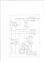
No evidence of burning out, anywhere, any got a circuit of the power supply/protection PCB
thannks
Mine has died and the power goes to both PCBs, The 48V relay simply no longer goes on? All six 100uf caps gone a bit high, repalced them and all the transistors test ok. even the relay driver one tests ok.
all resistors Ok, even with the power PCB's not connected the relay still will not operate but with no circuit that may be normal for this thing
No evidence of burning out, anywhere, any got a circuit of the power supply/protection PCB
thannks
Has anyone got any info on the protection circuit?
Did anyone have any Power Supply details on this?
I have one to fix. It all works but the Relay never clicks. Does it use the Normall Closed contacts and 'Open' the connections if a fault is detected?
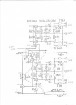
A schematic would be appreciated.
P.
Electro 25watt
Relay does indeed open under fault.
To check operation disconnect amp boards and ground sensor marked E. Then touch sensor A(B) to +26 volt line. Or C(D) to -26volt line. Relay should then trigger.
Relay does indeed open under fault.
To check operation disconnect amp boards and ground sensor marked E. Then touch sensor A(B) to +26 volt line. Or C(D) to -26volt line. Relay should then trigger.
Attachments
Electro 25watt
Sorry never did get the factory recommendation.
I generally set for max 500mv across the resistor or test points. But this is pretty well max. Achilles heel of this amp is heat and the poor way the transistors are mounted close together so heat cannot be dissipated. For peace of mind perhaps you should set a little below that figure and use the back of your hand on the heatsinks as a guide.
BD203 output transistor failed!
One of the BD203 transistors in my "Electrocompaniet 25W class A" has gone open circuit would it be advisable to replace all the output transistors?
If I need to replace all the output devices I'm looking for 2 x BD203 and 2 x BD204 transistors original or suitable equivalents.
I've seen "Inchange Semiconductor Company Limited" are remaking them but can't find where to buy them in the uk.
Sharif.
- Home
- Amplifiers
- Solid State
- Electrocompaniet original 25 W needs help