Sorry for the question-dumping... :-/
MikeB !
- Why dont you use nothing emitter-degeneration resistors in the 1st stage ?
- With 2N5401/2N5551 in the triple-darlington whats the max rail voltage in SOA ?
- The enhanced wilson current mirror with 3 bjt at the VAS may improve the sound, or it isnt critical here ?
- Do you have any measured or simud phase diagram about your amp ?
- Dont you want to try a cascoded CCS for the 1st stage ?
(From the moment that i readed the peufre site, i'am curious about this, and i'am trust in your experiences)
Hi, Mike,
You make this before or after the CFP differential input design of yours?
EDIT : The company is still active, making full line of audio power amp till now.
You make this before or after the CFP differential input design of yours?
Interesting tought. I also look the driver of final stage is driven not-ordinary way. The driver has R to opposite rail supply, not to Emitor of opposite driver. Could be these 2 contributes to Electrocompaniet sound?I wonder wether using output signal from both side of the diff amp cancels 3rd overtone and could be the contribution to the good sounding of this topology with current mirror VAS?
EDIT : The company is still active, making full line of audio power amp till now.
Re: Sorry for the question-dumping... :-/
I've designed this circuit for +/- 36volts, but the 2n5401/2n5551
is capable of 150volts, giving ~+/-70volts. But then the diffamp
needs to be replaced. mpsa18 has a maxrating of 45volts,
the bc546 65volts.
I've measured "perfectly" balanced currents, so the currentmirror
seems to work fine enough. I could try the cascoded ccs.
Phew, this CFP-thing is quite long ago ! I've designed this one a
few weeks ago, and have built it last sunday.
Mike
Cortez said:MikeB !
- Why dont you use nothing emitter-degeneration resistors in the 1st stage ?
- With 2N5401/2N5551 in the triple-darlington whats the max rail voltage in SOA ?
- The enhanced wilson current mirror with 3 bjt at the VAS may improve the sound, or it isnt critical here ?
- Do you have any measured or simud phase diagram about your amp ?
- Dont you want to try a cascoded CCS for the 1st stage ?
(From the moment that i readed the peufre site, i'am curious about this, and i'am trust in your experiences)
I've designed this circuit for +/- 36volts, but the 2n5401/2n5551
is capable of 150volts, giving ~+/-70volts. But then the diffamp
needs to be replaced. mpsa18 has a maxrating of 45volts,
the bc546 65volts.
I've measured "perfectly" balanced currents, so the currentmirror
seems to work fine enough. I could try the cascoded ccs.
lumanauw said:Hi, Mike,
You make this before or after the CFP differential input design of yours?
Phew, this CFP-thing is quite long ago ! I've designed this one a
few weeks ago, and have built it last sunday.
Mike

Hi lumanauw !
It's quite simple, i wanted a simple circuit for my subwoofer and
wanted to try something that is much easier to build (as it does not
need complementary matching). But suddenly sims were promising,
i assembled it and was very surprised with the sounding !
This means: Simple circuit -> fast, fast -> good sounding...
Okay maybe not that simple !
Mike
Hi, Mike,
1. Gain of first stage (differential)
2. Gain of this current mirrored VAS
3. Output impedance of current mirrored VAS
just by looking at the schematic (without simulator)?
I dont have simulator. Could you teach me how to calculateOpenloopgain is ~1:5000, makes ~1:20 for 1st stage, 1:250 for 2nd.
1. Gain of first stage (differential)
2. Gain of this current mirrored VAS
3. Output impedance of current mirrored VAS
just by looking at the schematic (without simulator)?
Waw. Where can I read that?the Anthony Holton N-channel amplifier sounded better than Electrocompaniet.
N-channel
I will rate my n-channel amp among top 10, maybe top 5 solid state amps that money can buy...!
I used good quality parts, and used much time matching them, nothing exotic.
PSU is dual-mono, 2x 38v 625va, 4 x 22 000uF RIFA, dual bridges
pr. channel.
No Electrocompaniet amp (that I have heard) can touch it...
Arne K
adason said:anybody actualy built this?
http://users.otenet.gr/~athsam/electrocompaniet.htm
i am realy tempted now
Mmm, post 16.
lumanauw said:Hi, Mike,
I dont have simulator. Could you teach me how to calculate
1. Gain of first stage (differential)
2. Gain of this current mirrored VAS
3. Output impedance of current mirrored VAS
just by looking at the schematic (without simulator)?
Hi lumanauw !
A must admit, i'm a sim-junkie... So calculating gains from schematic is not my strength.
Biasing ? yes. Gain ? maybe aproximate. Bandwidth ?, no.
first stage: assuming virtual internal emitterresistor of 20ohms,
gives 680/20 = 1:34. But as the output is loaded gain is reduced.
Calculating from hfe of 2nd stage the 680ohm needs to be reduced.
Vas using currentmirror or ccs has theoretically infinite gain. But
deviceleakages and load to the vas limits it. As i have 100k to ground,
gain should be 100000/(150+20) = 588.
But the outputstage puts load to it.
As i use both outputs from diffamp the gain should be twice.
openloopgain should be 34*588=20000. But according to sim
it's only 5000. So my calcs are wrong about 1:4 !
Maybe anybody else can do better ?
Output impedance would be infinite. The 2 100k reduce it below 50k.
Mike
MikeB said:
first stage: assuming virtual internal emitterresistor of 20ohms,
gives 680/20 = 1:34. But as the output is loaded gain is reduced.
Calculating from hfe of 2nd stage the 680ohm needs to be reduced.
Vas using currentmirror or ccs has theoretically infinite gain. But
deviceleakages and load to the vas limits it. As i have 100k to ground,
gain should be 100000/(150+20) = 588.
But the outputstage puts load to it.
As i use both outputs from diffamp the gain should be twice.
openloopgain should be 34*588=20000. But according to sim
it's only 5000. So my calcs are wrong about 1:4 !
Maybe anybody else can do better ?
Output impedance would be infinite. The 2 100k reduce it below 50k.
Mike
Hi MikeB,
Your gain calculation is OK! For more sophisticated result You can calculate with the input impedance of the second stage, which is about 15kohms (150ohmsxhfe) I calculated the hfe with about 100. So You have to reduce the 680ohm with the parallel 15kohms. So what You calculated, is the no loaded open loop gain. So it would be great to see how the load is reduce the gain. As I found triple EF with 2x22kohms load results 4% less gain with 4ohms load.
Mark Levinson made this configuration, but with cascode on the input stage, emitter follower between the stages, and cascoded VAS, with Wilson type current mirror. They used MJE15030/31 with about 60mA current for VAS. The Levinson amp contains 5times more transistors...
sajti
Hi, Mike,
Thanks for the tip.
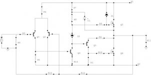
If the Nch amp is like this, I think it will be the same as ordinary amp. We can still consider the output as ordinary pushpull totem pole, with Q1 as the inverter for lower Nch, and bias is set by D2.
Thanks for the tip.
I see one of possible strength in Electrocompaniet is in the final stage. The driver is connected to CCS to opposite rail.No Electrocompaniet amp (that I have heard) can touch it...
If the Nch amp is like this, I think it will be the same as ordinary amp. We can still consider the output as ordinary pushpull totem pole, with Q1 as the inverter for lower Nch, and bias is set by D2.
Attachments
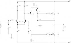
But if the Nch is like this, I think it is differ than ordinary pushpull totem pole output stage.
The bias is set by R8, so there is no VBE multiplier connected between VAS.
This topology also has the same operating charactistic between Q5 and Q6 (operated in the same way).
Is this Nch topology better than ordianary pushpull totem pole output stage due to symmetrical operation of Q5 and Q6? What other excel does this topology has?
I also wonder, if this Nch topology has non-turnoff properties of the final stages? Due to not-using VBE multiplier for bias adjustment?
But I cannot think how to exclude the output stage from NFB loop if I use this topology. In ordinary amp, I can simply take the feedback point from VAS to exclude the output stage from NFB loop. How to do it in this topology?
Attachments
- Status
- This old topic is closed. If you want to reopen this topic, contact a moderator using the "Report Post" button.
- Home
- Amplifiers
- Solid State
- Electrocompaniet, how does it sound?