Hi all,
I had a request from meanman1964 on a private message :
Hi Marc ,
Looking forward of building this amp .Ordered the parts at Mouser and Banzai music .
Gonna use my EL 34 Golden Dragons for this amp .
The only sad thing for me regarding your board is that I can't use a separate HV-PSU .
Are you planning a new layout that's having this possibility ?
Regards
Patrick
I will answer here since as I have already said: "Please put the technical questions on this forum because it can help every body"
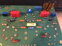
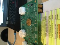
There is absolutely no problem to use a high voltage DC power supply with this PCB, the input bridge will be redundant, you will only loose 2 x o.7 V through the two rectifiers ! This is the safe solution
If you want to avoid this, you can replace D1 and D3 by a wire and DO NOT CONNECT D2 and D4, you will have the + HV on the right input os the connector (indicated AC) and the -HV on the left side (near R27). This is not a safe solution because if you make a wrong connection, you will destroy the amplifier
You can see the PCB layout in the attachement.
Cheers,
Marc
I had a request from meanman1964 on a private message :
Hi Marc ,
Looking forward of building this amp .Ordered the parts at Mouser and Banzai music .
Gonna use my EL 34 Golden Dragons for this amp .
The only sad thing for me regarding your board is that I can't use a separate HV-PSU .
Are you planning a new layout that's having this possibility ?
Regards
Patrick
I will answer here since as I have already said: "Please put the technical questions on this forum because it can help every body"
There is absolutely no problem to use a high voltage DC power supply with this PCB, the input bridge will be redundant, you will only loose 2 x o.7 V through the two rectifiers ! This is the safe solution
If you want to avoid this, you can replace D1 and D3 by a wire and DO NOT CONNECT D2 and D4, you will have the + HV on the right input os the connector (indicated AC) and the -HV on the left side (near R27). This is not a safe solution because if you make a wrong connection, you will destroy the amplifier
You can see the PCB layout in the attachement.
Cheers,
Marc
Attachments
Hi,
I have a new request on PM Please use this forum for technical question ! PM are only for confidential private message, I will not respond to technical questions sent by PM anymore and my box is nearly full...
Question from potepuh:
"Hello
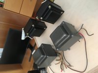
I am about to built a baby hue with the 6550 or 6V6 will this transformer be apropriate? FS: Pair of Hammond 1628SEA HIFI Single-Ended Output Transformers In EU. or I should by the toroidy?
Thanks! Sebastjan"
No this transformer is for single ended amplifier as indicated and it is not designed for Push-pull output You need the recommended Toroidy or if you prefer Hammond : the 1650N.
Rgds,
Marc
I have a new request on PM
Please use this forum for technical question ! PM are only for confidential private message, I will not respond to technical questions sent by PM anymore and my box is nearly full...Question from potepuh:
"Hello
I am about to built a baby hue with the 6550 or 6V6 will this transformer be apropriate? FS: Pair of Hammond 1628SEA HIFI Single-Ended Output Transformers In EU. or I should by the toroidy?
Thanks! Sebastjan"
No this transformer is for single ended amplifier as indicated and it is not designed for Push-pull output
You need the recommended Toroidy or if you prefer Hammond : the 1650N.Rgds,
Marc
Nice design!!
There's something I don't get from the wiki.
"The outputs must be high gm devices which will tolerate largish Rg1 values. That limits us to Cathode biased EL84 or if using fixed bias".
High gm means high maximum grid resistance?
Why only EL84?
EL34 has same or slightly higher transconductance, and can use a 700 kohm grid resistance.
Even KT88 can use 470 kohm, cathode bias (and its gm is similar to that of the EL34)
Just 6L6 and 6V6 are not suitable, according to that requirement.
Even power triodes like 2a3 and 300b can use 470k grid resistance (even though their gm are less than half of that EL84).
It is not only EL84
The thread started with EL84 because the original design was based on an ECL86 which was unfortunately no more produced and therefor Ian replaced the two difficult to find ECL86 by an ECC83 and two EL84...
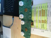
I have designed 3 different PCB for the Baby Huey :
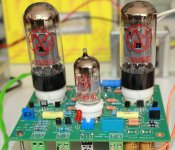
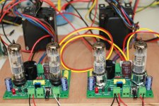
1) A simple version with two cathode biased PCL86 (equivalent to the ECL86 with a different heater voltage and easier to find) see photo...
2) The official EL84 third version with MOSFET source follower and fixed bias...
3) The octal output tube ultimate version with same MOSFET driver and fixed bias for EL34 or equivalent tubes!
There were many different version with the EL34 or 6CA7, the KT88, and even the 6V6 which work very well (see photo) and more than 200 PCB were produced with octal output sockets
Rdgs,
Marc
The thread started with EL84 because the original design was based on an ECL86 which was unfortunately no more produced and therefor Ian replaced the two difficult to find ECL86 by an ECC83 and two EL84...
I have designed 3 different PCB for the Baby Huey :
1) A simple version with two cathode biased PCL86 (equivalent to the ECL86 with a different heater voltage and easier to find) see photo...
2) The official EL84 third version with MOSFET source follower and fixed bias...
3) The octal output tube ultimate version with same MOSFET driver and fixed bias for EL34 or equivalent tubes!
There were many different version with the EL34 or 6CA7, the KT88, and even the 6V6 which work very well (see photo) and more than 200 PCB were produced with octal output sockets
Rdgs,
Marc
Attachments

Hi Patrick,
I don't understand your question ? Which mistake are-you speaking about ? I think it is completely explained in the following documents
Marc
I don't understand your question ? Which mistake are-you speaking about ? I think it is completely explained in the following documents
Marc
Attachments
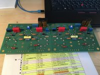
The component number of the bias trimmers.
When you look at the board, the side of V2 the trimmer is R42 in the building doc you say R43 on the side of V3 the trimmer is R41 in the building doc you say R42
When you look at the board, the side of V2 the trimmer is R42 in the building doc you say R43 on the side of V3 the trimmer is R41 in the building doc you say R42
Attachments
Last edited:
Yes ! "trimmer R41(board) is to set bias of V2 and trimmer R42(board) is to set bias of V3" !
R43 is a typo error, of course it's R41 but since the picture was clear enough to understand the procedure, nobody from the GB 1 reported this error
But, to make a better documentation, I have corrected the two documents and I add them to this post...
Marc
R43 is a typo error, of course it's R41
but since the picture was clear enough to understand the procedure, nobody from the GB 1 reported this error But, to make a better documentation, I have corrected the two documents and I add them to this post...
Marc
Attachments
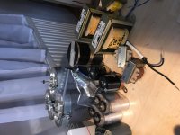
Is a toroid of 60V/0,5 okay for the mosfet driver stage and the negative bias of the output tubes of both channels?
I mean 60Vac/0,5 A
Hi bekim,
5) Yes, you can use a 4k transformer and 40 W will be enough if you don't push your amplifier with more than 400 V anode voltage ! I recommended a Toroidy 4k 80 W output transformer : TTG-KT88PP TOROIDY - Transformateur: de haut-parleur | TME - Composants electroniques
Cheers,
Marc
Marc , why's that ?
I'll use the EL34 tubes and probably stay under the 400Volts , normaly I can use a EL34PP OPT right ?
- Home
- Amplifiers
- Tubes / Valves
- EL84 Amp - Baby Huey