Thanks!The 4R7 resistors were just to provide a little separation between the supplies for the two channels.
Don't obsess about getting the B+ down too much. 350 or 360 V would be OK.
Tube circuits are +/- 10% at best on any parameter you care to pick.
Cheers,
Ian
I hope to start working on the chassis this weekend and thought I would check and see is anyone spots any potential problems with my planned layout.
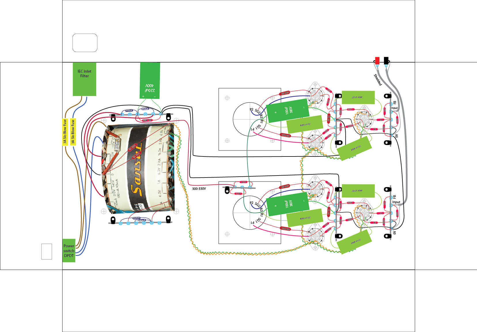
Not having a lot of experience I made a wiring plan on the computer. Not completely done yet and it doesn't show the auxiliary circuits, I'll do them on perf board.
-Brad
Not having a lot of experience I made a wiring plan on the computer. Not completely done yet and it doesn't show the auxiliary circuits, I'll do them on perf board.
-Brad
Attachments

I hope to start working on the chassis this weekend and thought I would check and see is anyone spots any potential problems with my planned layout.
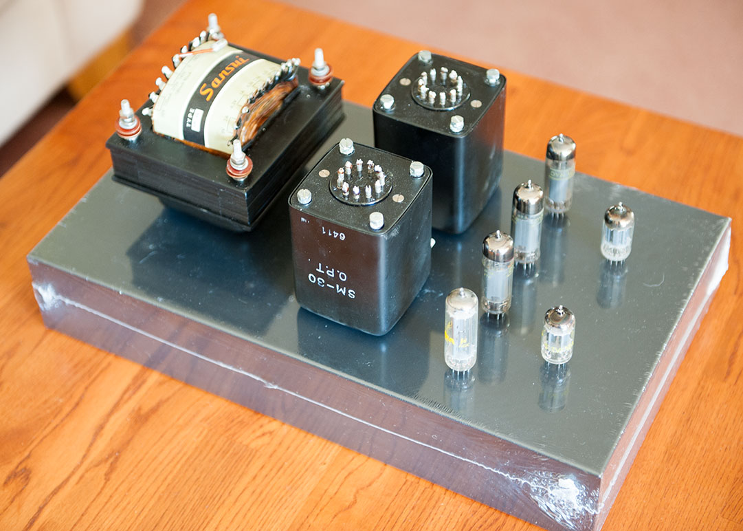
Looks like the vacuum escaped from one of your finals.
Those tubes were just used for my mock up, I wanted to visualize my planned layout.Looks like the vacuum escaped from one of your finals.
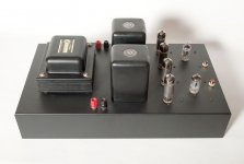
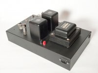
Here is the chassis with the metal work done, I hope to start soldering this weekend.
Attachments
Ian,Just Use the 275-0-275.
That will give a B+ which is a bit high (probably around +350V to 360V).
The 47 Ohms resistors were reduced to 4R7 which is noted on thread somewhere. Not sure which 220K you mean but it won't affct the B+ (which ever it is).
I am assuming that you are building the basic BH with the CCS Bias blocks on the output tube cathodes. For that higher B+ then change the current set resistors in the Bias blocks from 16 Ohms up to 22 Ohms. That will set idle currents to 29.5mA and keep output tube dissipation within limits.
The tranny rating of 180mA is a little light but should be OK.
Cheers,
Ian
I think I read in an earlier post, someone else had a higher than ideal B+ and you recommended adjusting the screen resistor on the output tube. Is that something I should do?
-Brad
I checked to see what I had specified as screen resistors. 150 Ohms. At higher voltages it may be worthwhile increasing these a little although they are primarily there for a "screen stop" function (suppresion of parasitics) rather than for screen grid protection. Maybe use 270 Ohms.
I have never built a HiFi Power Amp, either tube or SS which did not benefit from separate power supplies for each channel, but size and cost and weight are the trade offs.
Cheers,
Ian
I have never built a HiFi Power Amp, either tube or SS which did not benefit from separate power supplies for each channel, but size and cost and weight are the trade offs.
Cheers,
Ian
I checked to see what I had specified as screen resistors. 150 Ohms. At higher voltages it may be worthwhile increasing these a little although they are primarily there for a "screen stop" function (suppresion of parasitics) rather than for screen grid protection. Maybe use 270 Ohms.
Cheers,
Ian
Thanks Ian, I have made a lot of progress over the weekend.
I have updated the original scematic for the high B+ and 8 ohm taps on the OPT.
I now have 22R for the current set resistors, 270R for the screen grid resistors and 17K for the feedback resistors.
-Brad
major error
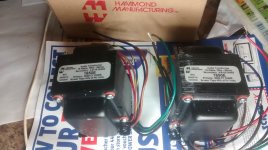
Thought I should message this so as to stop any one else making same mistake. I bought some Hammond 1650e's thinking their frequency range went down to 30hz....They only go to 70hz!!!! Luckily they were half price, so it could of been worse...Big set back for me...might just have to build as a single power source amp now...win some: lose some
Thought I should message this so as to stop any one else making same mistake. I bought some Hammond 1650e's thinking their frequency range went down to 30hz....They only go to 70hz!!!! Luckily they were half price, so it could of been worse...Big set back for me...might just have to build as a single power source amp now...win some: lose some
I originally build with 1650Es and were happy with them.
I changed to James JS6228HS to see if that made things better with a transformer that would be more lightly loaded and hence, I thought, further from any saturation non-linearity (but mostly just because I wanted the aesthetics of the encapsulated package and I was making an excuse for myself to spend the extra money).
There was no great parting of the fog and any slight difference might have been purely imagined. I felt that, if anything, the difference was of increased "brightness", which would have been all about the top end rather than the bass.
I changed the sound more by fiddling with different tube combinations.
The frequency response (frequency range) is measured (usually) at the points where it drops 3dB from the flat bit in the middle. That gradual drop starts to happen before you get to those 3dB down locations, so there will be some smaller range between 2dB limits and still smaller range for 1dB limits. The further apart you can make the 3dB limits, the flatter the bit through the range you're interested in will be.
The other aspect of this is that as the response drops off, so does the phase change. So the further out the 3dB response can be pushed, the flatter the phase response through the pass band will be. And the flatter the phase response, the better the matching will be between left and right channels, and that makes the stereo imaging more accurate.
That's my understanding anyway. If I am wrong, I look forward to someone explaining in detail what's really going on, and I will learn something new!")
The other aspect of this is that as the response drops off, so does the phase change. So the further out the 3dB response can be pushed, the flatter the phase response through the pass band will be. And the flatter the phase response, the better the matching will be between left and right channels, and that makes the stereo imaging more accurate.
That's my understanding anyway. If I am wrong, I look forward to someone explaining in detail what's really going on, and I will learn something new!
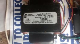
Here are the units with spec labels.
I'm not making excuses for Hammond but those are the only 1600 series outputs I've seen that have a label like that. All of the others I've seen and that I could find online say 30 - 30KHz. They also have a different label format to others that I could see. Perhaps they're older models with the same number. Some Hammond guitar amp transformers say 70Hz to something.
The Hammond Site says this about all of their 1650 series outputs:
Frequency response 30 Hz. to 30 Khz. at full rated power (+/- 1 db max. - ref. 1 Khz) minimum.
I'm not a Hammond fan but I have used these transformers in the past and they definately do not roll off that early. However, I no longer have the measurements.
Maybe someone with a particularly warped sense of humour is doing knock offs of the 1650's.
- Home
- Amplifiers
- Tubes / Valves
- EL84 Amp - Baby Huey