the usual stuff
Hi to all!
Let me start with Tubelab.com -- apologies accepted and no offence actually taken. You got yourself on the "hit list" just because you echoed other people's sentiment. Noone is without loose ends, and the fact that your site advocates what I "fight" (not literally, but conceptually, of course) i.e. hybrids and rare tubes, as well as the fact that your name is not listed -- therefore to me you are still a person without name (if it's you on the photo, than we know how do you look like, although it might be your cat on the photo, for that matter... or another person) -- so you got your mention in my post.
But, the usual pity is that those persons who were called to respond, and who initiated this impulsive post, AS USUAL, kept low. The patronizing guy who dismisses other people's eventual knowledge of physics, statistics, or whatever, and advocates his own as the only truth available -- and the Jakarta guy who does not understand "idiomatic expressions" or whatever -- well, those stayed put, most probably have other things to do (other b...s to break, whatever).
When it comes to whether does it affect the sound, I am almost certain that it DOES AFFECT, but point is, whether we can measure the effect, and whether most audiophiles and DIY-ers can hear the difference, not because they do not have good enough ears, but because their system (room counted in) is not up to the task.
Regards to all,
Aleksandar
But, the usual pity is that those persons who were called to respond, and who initiated this impulsive post, AS USUAL, kept low.
Actually, there may not have been anything to respond to. Just raw assertion of superiority, and how does one answer that?
I have just re-read the thread and am leaning towards agreement with SY. Currently half of it has nothing to do with where to connect G3 and a lot of nitpicking over semantics (and I'm really trying to be graceful here).
Besides, I, who do not have a name on these forums and 'hide behind a pseudonim', but know some elementary physics, would think that creating a rather different electric field gradient across K to P, having changed the voltage on G3 by a couple hundred V or so, would create much more of an impact on sound than transit time considerations. It should be a 'relatively simple' matter to draw some curves with G3 connected to K and then to P and look at the difference. Given how 'sparse' G3 is compared to G1 and G2, the difference probably will not be much, but it should be visible - and, I would say, that is what will change the sound.
Finally, how does one's personal philosophy of using SS hybridization, or not, impact the strength of one's arguments for the purposes of this thread? I sincerely believe that discussions along the lines of 'my kung-fu is better than yours', in which proponents of some 'one true way' of deign infer they are better suited to know, notice or understand what 'better sound' is, should be kept well off this forum - if those are to one's liking, I would recommend audio asylum as the place to do some reading along those lines.
OK, I don't proclaim to have a deep understanding of physics, but I do have a good collection of tubes and electronic equipment and the knowledge to use it. This what I CAN and will do. I will get an EL-34 tube. And plot the curves with G3 connected to the plate, and the cathode. I will also explore the "high Mu triode" connection that I mentioned earlier. I have just begun to set my lab back up, so it might take a few days. I will put the results here when done. I just got to listen to my audio system last night for the first time in almost a month.
Yes, it's me in the photo. And my name is George Anderson. The "kung - fu" antics of the audio asylum is exactly the "stuff" that I would like to avoid. This forum is a place for a free exchange of ideas. I will continue to add mine as long as they are welcome.
Yes, it's me in the photo. And my name is George Anderson. The "kung - fu" antics of the audio asylum is exactly the "stuff" that I would like to avoid. This forum is a place for a free exchange of ideas. I will continue to add mine as long as they are welcome.
...This forum is a place for a free exchange of ideas. I will continue to add mine as long as they are welcome.
Well, I will take the oportunity to thank you for that - as i may thank Alex Kitic as well. I just wanted to point out this is not a competition.
BTW regarding the high mu connection it seems tome that it's usefulness may be limited only to certain pentodes. Looking at the pentode curves for the EL34, driving G2 negative will probably produce very flattened down curves which certainly lead to a high mu but wether you will actually be able to get any power from this connection seems doubtful. Be that as it may, I am eagerly anticipating your results.
Also, during my research on this forum and elsewhere, on screen grid drive (the EL34 being rather unsuitable for this, though), I saw mention of manipulating G3 voltage to change the curves, the reference in question was about changeing pentode characteristics and was alo brought up in conjunction with G2 drive. Unfortunately I do not remember which tube was in question, but it was a straight pentode. The oltages on G3 that were tossed around were in the range of +-30V WRT cathode. This suggests that another connection may be explored, where G1 and G3 are conencted together.
I still wonder if the main difference between the two connections is in high frequency behaviour more than linearity. If I recall the text book rational for G3 was to drain the cloud of electrons formed between A and G2 when they struck the former with sufficient energy to 'bounce back' or dislodge others from the anode's surface. I also recall (I'm new here, someone who knows better please correct if I'm wrong!) G3's wire pitch was too wide to effect any real control on the stream of high energy electrons heading for the plate.
In most triode connections G2 and A are at the same DC potential so I can't really grasp how the electron cloud inbetween impacts overall tube behaviour. It's a fair guess though that one way it does is the same way as in pentode mode, by altering capacitance. And the effects of capacitance are normally felt at high frequencies. A G3-A connection has no impact on that cloud, a G3-K connection would appear to suppress to some degree. Does that make sense?
In most triode connections G2 and A are at the same DC potential so I can't really grasp how the electron cloud inbetween impacts overall tube behaviour. It's a fair guess though that one way it does is the same way as in pentode mode, by altering capacitance. And the effects of capacitance are normally felt at high frequencies. A G3-A connection has no impact on that cloud, a G3-K connection would appear to suppress to some degree. Does that make sense?
When an electron hits the anode it is travelling at such a high velocity that it can dislodge an electron from the anode material. This is known as secondary emission. The problem with secondary emission (and the reason why you don't see pure tetrodes any more) is that if the anode voltage is quite low compared to the g2 voltage, an electron dislodged by secondary emission can be attracted to g2, causing a negative slope in the anode curves. As anode voltage rises, secondary emission falls, so the effect is that there is a dip in the anode curves at low voltage. The problem with the dip is that the negative slope on one side implies negative resistance, and that can cause oscillation. Placing g3 (often known as the suppressor grid) in between g2 and the anode prevents secondary emission because it screens g2 from the low velocity secondary electrons. Thus, the negative resistance region is avoided.
Beam tetrodes don't have a suppressor grid but they focus their electron stream into beams so that the incoming high velocity electrons repel the low velocity electrons, forcing them back to the anode. The region near the anode that accomplishes this repulsion is sometimes known as a virtual cathode. A nice side-effect of the beam tetrode is that the anode can usually swing closer to 0V than a pentode, increasing efficiency in an output valve.
Beam tetrodes don't have a suppressor grid but they focus their electron stream into beams so that the incoming high velocity electrons repel the low velocity electrons, forcing them back to the anode. The region near the anode that accomplishes this repulsion is sometimes known as a virtual cathode. A nice side-effect of the beam tetrode is that the anode can usually swing closer to 0V than a pentode, increasing efficiency in an output valve.
It's something I'ld like to investigate further if I ever get adequate test gear. My audio generator is limited to 120 kHz, not high enough to catch the differences between G2 and G3 connect on, for example, the E180F fronting my EL84 plaything. Both connects are less than a dB down at the top, and I'm not certain that droop isn't caused by probe lead capacitance.
Tubemaster,
Thanks for your valuable contribution to my original question.
I'll be running the EL34s with G3 connected to cathode to avoid that spray of high order harmonics which shows up in the spectrum analyser outputs you posted.
In hindsight its probably a good idea anyway as it allows me the option of substituting 6550 or KT88 etc.
For those who have been wondering what all the talk/arguement/physics instruction about transit times and such is about
PHYSICS ABSURDIUM (The divil made me do it)
- electrons will take different paths between cathode and anode and so different electrons transverse different path lengths. There will therefore be a spread in transit times. This transit time spread defines the risetime of a signal and therefore the uper frequency limit. How this is affected by where we connect G3 - well er... I'm still non the wiser and I did (usually) stay awake in physics class. Someone above has quoted an electron transit time of 1.3 nano-second. Assume a 10% spread in transist times (usually it more like 6%) to give a rise time of 130ps which corresponds to a frequency limit of about 2.5 GHz. I like good high frequency response in my audio amps but thats a smidge beyond my output trannies capability.
Of-course many other factors act to limit high frequency response long before transit time effects come into play.
Cheers,
Ian
EC8010 said:I've never seen anything to suggest that g3 affects Cag, but it's certainly dramatically reduced by the inclusion of g2. I suppose one could try measuirng the input capacitance of a pentode with g3 connected alternately to anode or cathode.
IIRC, in most pentodes, g3 is a very coarse winding, i.e., small area, thus small contribution to capacitance one way or the other.
Here are the curves
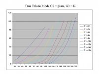
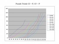
Ok, I looked around and I have no EL-34's in the warehouse, so I "borrowed" one from one of my amps. It is a genuine Mullard (Scott branded) made in 1960. Because of the value of this tube I had to refrain from my usual "crank it till it glows' methodology.
I plotted both sets of curves with G2 tied to the plate through a 150 ohm resistor. The first set of curves has G3 tied to the cathode through a 150 ohm resistor. The second set of curves has G3 tied to the plate through a 150 ohm resistor. In both cases the "plate" current includes the G2 current, and in the second case it also includes the G3 current.
The results surprised me. I can only assume that the non-linearities that were encountered in the second plot are caused by secondary emission effects. This thread raised some (often emotional) debate over which should be the preferred connection. These plots should settle this issue. When I have some time I will repeat this test using an 807, which is a beam tube with a seperate G3 pin.
Attachments
tubelab,
Thanks for the data - the recommendations I saw (can't remember where now) were to put 330R from G2 to Anode and 1K from G3 to Anode.
In your next idle moment you may wish to see if that changes anything. Meantime I'll stick to G3 to Cathode connection which seems to be what all results to date have shown as superior.
I've actually swapped from EL34 to 6550 on my test amp so for me at least the question has become moot to some degree.
Cheers,
Ian
Hi Tubelab,
thank you very much for those interesting graphs! I would not have expected such a big difference, though. And I doubt a bit that it really is due to secondary emission effects because then any real triode would show those kinks in their plate curves, too, no?
Also, it would be most interesting to see what happens when g3 simply would be left disconnected.
I did some curve sheets of trioded pentodes/tetrodes myself and always used (when g3 was available at a pin) the g3 to plate connection:
Some plate curves of triode strapped pentodes/tetrodes
Tom
Well tubelab, I'm not sure wheather to thank you! Laundry was done, the test gear packed away and I was ready to kick back with an evening movie when I saw your post. Instead I ran a series of distortion measurements on the driver stage of an amp I'm playing at designing. The results aren't exactly comparable (see below) but do present an interesting contrast to your results.
The tube is a grid-leak biased E180F with an IXYS chip as plate load. The output tubes were removed, leaving 220 kohm resistors in parallel with the test set - an Audio Precision Portable One - as the tube load. The One's analyser input impedance is 100 kohm, so the total load impedance on the E180F was just over 68 kohm (!). The driver shows a definite distortion null with plate current right in the 10 ma range which didn't change between the two connections. Current was confirmed at 9.9 ma for both runs.
Distortion measurements were done on two variations of G3 connection. The second had G3 tied to cathode (effectively ground because of the grid-leak topology) via an 820 ohm resistor. The first set of data used a slightly unconventional G3 to G2 connection, still using 820 ohms. It represents the current state of the amp and the version I wanted to compare. G2 goes to anode via 120 ohms, so it's arguably 'close enough' to pseudo triode.
The results are tabulated on the attached PDF. For the most part the only solid conclusion I can draw is the E180F is an amazing little tube. The cathode-grid voltage in grid-leak is about 0.45 Vdc, so some of these runs pounded the grid pretty hard positive. In terms of the differences between the two G3 connections, most appears to fall into the realm of experimental error. The THD results at half a volt are generally better for G3 connected to cathode, however decreasing the analyser high frequency rolloff to 22 kHz eliminates most of the difference for the 1000 Hz reading (a 22 kHz bandwidth invalidates the 10 kHz THD measuements.) Distortion drops to a third of the 80 kHz bandwidth measurements in both cases. What I suspect is happening is connecting G3 to cathode reduces some high frequency noise, since the analyser is really reading THD+N.
Oh, I also checked frequency response at the 120 kHz limit of my generator. Both connections were identical, again within experimental error. Neither connection showed any tendency to oscillate below the 60 Mhz limit of the scope.
Could this be tube dependent?
Attachments
- Status
- This old topic is closed. If you want to reopen this topic, contact a moderator using the "Report Post" button.
- Home
- Amplifiers
- Tubes / Valves
- EL34 Triode Mode - G3 where?