SY said:The main issue with your idea is gain- or lack thereof. You're replacing a gain block with a gain of roughly 50-60 with one of unity gain. I'd keep the input circuit as is and just add the filter as a separate stage.
so that would involve 9 tubes per channel (Low Pass and High Pass).
4 EL 34 (output), 2 6SN7 (phase splitter), 2 ECC83 or ECC88C (gain), 1 ECC88C 2 way filter (Steve Bench ckt)
right?
the filter could be fed by a Alps pot and a input selector. is there a need for any more tubes (I'm using a SS power ckt).
@navin
So we are talking here of an MTM configuration and bi-amping, correct?
I have built what is called "The Dayton 8's" MTM from Dave Tenney's site and they are fantastic! I've gotten a lot of compliments from them, esp. like "Will you build me a pair?" I said "sure" but until I "see" the money... On some good recordings plucked bass strings sound just like...plucked! And the low registers
www.wadsnet.com/~dtenney/dayton_8MTM.htm
Are you getting your ideas from here?
www.diyaudio.com/forums/showthread.php?threadid=59411
I know you have heard that bi-amping is the 'way' to go, but a well designed passive crossover is nothing to sneeze at. What you are proposing to do can be very complicated and wroth with a lot of trial and error and a few headaches, especially if this is first time (major) project. I'm not trying to sway you from what you want to accomplish, just some food for thought.
And as Sy posted, a separate unit for the 'tubed' crossover instead of building it directly in the same enclosure as the amp would be is what "I" would do IMHO.") And then there are much more possibilities in doing such; such as adjustable crossover/turnover frequencies, Q's, slopes: -6db, -12db, -18db and so on. Much easier to implement!
And then there are much more possibilities in doing such; such as adjustable crossover/turnover frequencies, Q's, slopes: -6db, -12db, -18db and so on. Much easier to implement!
Another thought but more expensive, but maybe not really, would be two separate units, one for the high, one for the low; and then either or both could be used on their own for use for different speakers or set-up. Plus you would be keeping the demands down for a single power supply. So now we are talking three separate units.
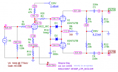
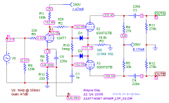
Anyway I'm posting an updated schematic using an ECC88 (my modified Koren's 6DJ8 model to better fit the Sylvania plate curves) which shows the NFB connection. Have you thought of using an ECC99 as the long tailed pair? Let me know your thoughts on this.
Cheers
Wayne
Edit: Of course in the updated schematic R6 (1k) would be bypassed and the gain would go up about 4dB. My goof up!
the speakers are:
tweeter Scan Speak 2905 9900, 90-91db
woofer Scan Speak 18W8546, 87-88db (push push)
So we are talking here of an MTM configuration and bi-amping, correct?
I have built what is called "The Dayton 8's" MTM from Dave Tenney's site and they are fantastic! I've gotten a lot of compliments from them, esp. like "Will you build me a pair?" I said "sure" but until I "see" the money... On some good recordings plucked bass strings sound just like...plucked! And the low registers
www.wadsnet.com/~dtenney/dayton_8MTM.htm
Are you getting your ideas from here?
www.diyaudio.com/forums/showthread.php?threadid=59411
I know you have heard that bi-amping is the 'way' to go, but a well designed passive crossover is nothing to sneeze at. What you are proposing to do can be very complicated and wroth with a lot of trial and error and a few headaches, especially if this is first time (major) project. I'm not trying to sway you from what you want to accomplish, just some food for thought.
And as Sy posted, a separate unit for the 'tubed' crossover instead of building it directly in the same enclosure as the amp would be is what "I" would do IMHO.
And then there are much more possibilities in doing such; such as adjustable crossover/turnover frequencies, Q's, slopes: -6db, -12db, -18db and so on. Much easier to implement!Another thought but more expensive, but maybe not really, would be two separate units, one for the high, one for the low; and then either or both could be used on their own for use for different speakers or set-up. Plus you would be keeping the demands down for a single power supply.
So now we are talking three separate units.Anyway I'm posting an updated schematic using an ECC88 (my modified Koren's 6DJ8 model to better fit the Sylvania plate curves) which shows the NFB connection. Have you thought of using an ECC99 as the long tailed pair? Let me know your thoughts on this.
Cheers
Wayne
Edit: Of course in the updated schematic R6 (1k) would be bypassed and the gain would go up about 4dB. My goof up!
Attachments
so that would involve 9 tubes per channel (Low Pass and High Pass).
4x EL34
2x 6SN7
1x ECC88 AF amp
1x ECC88 Crossover Hi/Lo
8 tubes total per side
Double for Stereo = 16 tubes
11.86 Amps @ 6.3V total filament curent.
8X EL34= 8A
4x 6SN7= 2.4A
4X ECC88= 1.46A
Not to mention all the plate current needed. One big *** power supply. The Lundahl LL1650 may fit your needs w/SS Bridge for HT but remember using a bridge w/cap input only 63% of rated current will be available, 93% w/choke input.
www.lundahl.se/pdfs/datash/1648__51.pdf
Cheers
Wayne
Not to mention all the plate current needed. One big *** power supply. The Lundahl LL1650 may fit your needs w/SS Bridge for HT but remember using a bridge w/cap input only 63% of rated current will be available, 93% w/choke input.
True and, if I were you, I'd plan on monobloc amps. Mine is a stereo unit with shared power tranny but it's only got 4 x EL34. For double that number, you're talking about a very heavy (and hot) unit. I think monoblocs offer a number of (obvious) advantages, e.g.
* Greater availability of suitable power trannies.
* Manageable weight.
* Less heat dissipation in each chassis.
* Ability to build one monobloc, then test/improve it, before starting on the next.
* Opportunity to place each power amp near the speaker it's driving.
Your preamp/crossover unit can be in one stereo chassis, feeding the monoblocs via separate interconnect cables. Grounding may require some extra care to avoid ground loops.
Costs of building monoblocs will be higher, of course, especially if you build four separate power amps for bi-amping; however, it will be more practical IMHO. Good luck!
cogsncogs said:
4x EL34
2x 6SN7
1x ECC88 AF amp
1x ECC88 Crossover Hi/Lo
8 tubes total per side
Double for Stereo = 16 tubes
11.86 Amps @ 6.3V total filament curent.
I like this. It requires 1 less tube (ECC88 replacing 2 ECC83) but will it have enough gain?
ray_moth said:
True and, if I were you, I'd plan on monobloc amps.
* Ability to build one monobloc, then test/improve it, before starting on the next.
* Opportunity to place each power amp near the speaker it's driving.
Your preamp/crossover unit can be in one stereo chassis, feeding the monoblocs via separate interconnect cables.
actually I thought about this and was really thinking of a 3 box design. 1. crossover and preamp 2. stereo power amps (one triode and one pentode). but my speakers are about 15 m away from where my electronics ae and i did not know where to divide the HIF87/ECC88 ckt and which tubes/parts should be in the power amp and which in the preamp.
now to reduce the size of the amp i am considering having hte powr transformer located in a seperate chassis and the power being fed to the amp via a cable.
i would build just one monoblock (based on the HIF 87 ) first. and after that is tuned then build 3 more mono blocks then build the 2 way crossover.
i do like cogsncogs idea of using 1 ECC88 instead of 2 ECC83 for a stereo pair but dont know of a schematic that implements this.
obviously i would have to build a stereo power amp to test this fullrange. and then build the ECC88C based 2 way crossover and feed each channel high pass and low pass singlas once the fullrange amp was tested.
Originally posted by: navin
actually I thought about this and was really thinking of a 3 box design. 1. crossover and preamp 2. stereo power amps (one triode and one pentode). but my speakers are about 15 m away from where my electronics ae and i did not know where to divide the HIF87/ECC88 ckt and which tubes/parts should be in the power amp and which in the preamp.
Forgoing the crossover unit for a moment.
For each stereo amp you will need (1) 6DJ8/ECC88/6922 as they are twin triodes. For two stereo units you will need only two, one in each stereo amp.
Now the crossover. You will need two 6922's, one for the left channel, one for the right. That's 2X 6922 for the crossover, 2X 6922, one for each stereo power amp, for a total of 4.
As in the schematic, that's one amp/driver stage that drives each channel, a total of 4. OUTA and OUTB as labeled on the schematic; OUTA goes to the top EL34, OUTB goes to the bottom EL34. Follow? If you'd like I can 'draw' out a complete schematic of each channel with the EL34's included. Maybe that may clarify things a bit. This is where you divide the HIF87 circuit.
As for gain, there is plenty; 43 to 44db should more than adequate. If you would like more gain (I don't think you will NEED it) you could use a 12AT7/ECC81 instead of the 6922's in the AF amp stage in each power amp. If you really need more gain, impliment it the "seperate" crossover unit, maybe another 6922 or even better a 5687 IMHO. Placing it in the power amps will just make for more noise and may complicate HF stability compensation. Plus using a higher mu tube such as a 12AX7/ECC83 will make for more "miller effect".
And by the way if you have or can obtain 6922's I would use those. Other tubes useful in that position would be 6N1P, 5965A, 12AV7, 6AQ8/ECC85, and many others but you may wish to stay with current production tubes.
The 5965's are becoming very popular again, so that will drive the price up here! A re-discovered tube.
So I hope you find some of this useful,
Wayne
I believe so. You have to calculate it. And/or, you can use a software as LTspice. It is one of the best simulator for analog electronic. I don't like much the shematic part, but the simulation program is excellent. And it's unlimited free software.will it have enough gain?

You can get it at: http://www.linear.com/company/software.jsp
It is optimised for both windows and linux with wine. With linux, you can even use the gEDA for the shematic work (and much more).
http://www.geda.seul.org/
As for the heat in an amplifier. It depend if you want to do a compact design or not. The main problem with a compact design is at the tubes are heating each other. As exemple, for a 6L6, you must have at least 15cm between 2 tubes. And they must not be near the transformers. So, if you have many power tubes, the amplifier will be quite large.
Another problem with many power tubes is the cablage. It is already not easy to have a noise free cablage with a simple amp, so it will become very complicated, if not impossible, with so many tubes in the same case.
cogsncogs said:
Forgoing the crossover unit for a moment.
For each stereo amp you will need (1) 6DJ8/ECC88/6922 as they are twin triodes. For two stereo units you will need only two, one in each stereo amp.
Now the crossover. You will need two 6922's, one for the left channel, one for the right. That's 2X 6922 for the crossover, 2X 6922, one for each stereo power amp, for a total of 4.
As in the schematic, that's one amp/driver stage that drives each channel, a total of 4. OUTA and OUTB as labeled on the schematic; OUTA goes to the top EL34, OUTB goes to the bottom EL34. Follow? If you'd like I can 'draw' out a complete schematic of each channel with the EL34's included. Maybe that may clarify things a bit. This is where you divide the HIF87 circuit.
And by the way if you have or can obtain 6922's I would use those.
Wayne
Wayne, it must be nice to have a town/city named after you (from your avatar).
from what i understand so far....for each channel (left and right)
1st we have and ECC88/6922 that feeds 2 6SN7. each 6SN7 feeds 2 EL34. this eliminates the ECC88 driver/AF stage as per your earlier post? Wow now we are down to 7 tubes per channel!
One of the reasons i am looking at tubes is that after all these years of listenting to SS I feel that every compoenent (SS amps have lots of components) adds distortion to the ckt. Tube amps tend to have fewer components. Even in my passive crossover i found that many components affected the sound esp high value caps (polyester) or high value (air core) inductors. it was usually the dynamics and realisim that was affected.
your idea is to have a 3 box design with the ECC88 and 6SN7 for both channels in box 1 and box 2 and box 3 essentially having 4 EL 34 each. right?
as far as the ECC88 availability goes I live in Mumbai (Bombay) India. the friend of mine who lives in Jamshedpur at the Eastern end of the country has promised to send me what i need. I can find out if they are available locally (in Bombay) when i get back from Singapore Jan 4th. Please PM me if I forget. I am getting senile fast.
Thanks so much for all your help.
Dominique_free said:
As for the heat in an amplifier. It depend if you want to do a compact design or not. The main problem with a compact design is at the tubes are heating each other. As exemple, for a 6L6, you must have at least 15cm between 2 tubes. And they must not be near the transformers. So, if you have many power tubes, the amplifier will be quite large.
Another problem with many power tubes is the cablage. It is already not easy to have a noise free cablage with a simple amp, so it will become very complicated, if not impossible, with so many tubes in the same case.
6" (15cm)! wow! I am not sure but i think in the 2 EL34 amps Ihave heard (Ella Consonance and Prima Luna Prologue 1) the tubes are closer together. What is the recomended distance between EL34?
I have chosen EL34 because the EL84 pentode would only give 15W which was not enoug for my woofer. I fear that even the EL34 30W pentode might be a bit short.
My OPT winder who makes OPTs fo Zen Audio amongst others in Singapore is not comfortable with making OPTs for EL34 PPP so I guess EL34 PP pentode is the most power I can get.
Also the highest voltage caps available locally are 450V. so I cant have any power ckt that requires caps of higher voltage for example the KT88 ckt I had required 600V caps.
Thanks again guys for all this. After I am done with this amp I intend to make some high sensitvity speakers and make an EL84PP since i already got those tubes so my tube fixation is going to continue for a while.
Anyone know of a small fullrange with 93db+ sensitivity and ability ot handle 15W? the ones I have looked at are Fostex 108 and Jordan JX92 both fall short. the speaker will be in a 150sq ft. room and should be a small floor stander (maybe a ML TL).
@navin
Yup! Also the county in which I reside is also Wayne County! I've had a lot of comments about that, even up/down here in the beautiful hills and mountains of West Virginia. One secret, not all of us are a bunch of dumb in-bred hillbillies Well I'm really from Ohio but the people there are mostly West Virginia and Kentucky transplants! And no I didn't marry my sister just a very distant cousin; by marriage that is.
Ok joking aside. With 450V supply and an appropriate output transformer you should be able to squeeze out 40 watts per channel in the UL configuration using a pair of EL34's with fixed bias. For a 450V HT you will need a min. 500V rated cap. You can do this by having two 250V-350V (I recommend 350V for a total of 700V) connected in series with a 100k 2W Metal Oxide // across each cap. Using two 350V caps connected this way will give you a 700V cap but the cap value will be half the value of each individual cap. Each cap should be of the exact same type, manufacture/brand and value, say 2X 470uF 350WV, which wired in series will give you a 235uF 700WV cap! See, easy! Just remember you have to shunt // each cap with a 100k 2W resistor to evenly balance the voltage across each cap!
Ok I have to leave my computer for a while so in the mean-time here's two links to two threads on our "Beloved Tube" forum where I have posted a few schematics of my current PP EL34 UL amp. Simple and adequate for the time being, produces kick-*** bass (balls) for a tube amp and fairly clean highs; HF ringing that's a product of the output trannies of which I hope to change soon to one of less leakage inductance. They must have high primary L and that explains the ample bass, but as with OPT design there are always trade-offs! Backing off from the original amount of NFB has cured it to an extent, now more forward sounding which can be more pleasing to the listener. But I like my amps to be on the flat uncolored side but with detail and air. Is that possible I may ask? I (we'll) keep trying!
Now the output stage of my amp would be close to yours but the input/driver stage will be like the one I've posted in this thread. So you would sub 1/2 of an ECC88 for one half the 6U8 (pentode section) and both units of the 6SN7 for the triode section of the 6U8, which then would connect to the EL34's. Have a look and write down your thoughts and questions and get back!
Here's the links:
Original thread:
www.diyaudio.com/forums/showthread.php?s=&threadid=40609&highlight=
Amp:
www.diyaudio.com/forums/attachment.php?s=&postid=470574&stamp=1094672647
Power Supply:
www.diyaudio.com/forums/attachment.php?s=&postid=509305&stamp=1100080737
Cheers
Wayne from Wayne in Wayne county!
The name of the road I live on is the same name as my Grandfather and Father also! G'day!
P.S. Sy, I eventually ended up buying as per your suggestion the Svetlana Winged "C" EL34's and had them in this amp since last June with no problems or complaints! Still going strong!
Edit: typo.
Wayne, it must be nice to have a town/city named after you (from your avatar).
Yup! Also the county in which I reside is also Wayne County! I've had a lot of comments about that, even up/down here in the beautiful hills and mountains of West Virginia. One secret, not all of us are a bunch of dumb in-bred hillbillies
Well I'm really from Ohio but the people there are mostly West Virginia and Kentucky transplants! And no I didn't marry my sister just a very distant cousin; by marriage that is.Ok joking aside. With 450V supply and an appropriate output transformer you should be able to squeeze out 40 watts per channel in the UL configuration using a pair of EL34's with fixed bias. For a 450V HT you will need a min. 500V rated cap. You can do this by having two 250V-350V (I recommend 350V for a total of 700V) connected in series with a 100k 2W Metal Oxide // across each cap. Using two 350V caps connected this way will give you a 700V cap but the cap value will be half the value of each individual cap. Each cap should be of the exact same type, manufacture/brand and value, say 2X 470uF 350WV, which wired in series will give you a 235uF 700WV cap! See, easy! Just remember you have to shunt // each cap with a 100k 2W resistor to evenly balance the voltage across each cap!
Ok I have to leave my computer for a while so in the mean-time here's two links to two threads on our "Beloved Tube" forum where I have posted a few schematics of my current PP EL34 UL amp. Simple and adequate for the time being, produces kick-*** bass (balls) for a tube amp and fairly clean highs; HF ringing that's a product of the output trannies of which I hope to change soon to one of less leakage inductance. They must have high primary L and that explains the ample bass, but as with OPT design there are always trade-offs! Backing off from the original amount of NFB has cured it to an extent, now more forward sounding which can be more pleasing to the listener. But I like my amps to be on the flat uncolored side but with detail and air. Is that possible I may ask? I (we'll) keep trying!
Now the output stage of my amp would be close to yours but the input/driver stage will be like the one I've posted in this thread. So you would sub 1/2 of an ECC88 for one half the 6U8 (pentode section) and both units of the 6SN7 for the triode section of the 6U8, which then would connect to the EL34's. Have a look and write down your thoughts and questions and get back!
Here's the links:
Original thread:
www.diyaudio.com/forums/showthread.php?s=&threadid=40609&highlight=
Amp:
www.diyaudio.com/forums/attachment.php?s=&postid=470574&stamp=1094672647
Power Supply:
www.diyaudio.com/forums/attachment.php?s=&postid=509305&stamp=1100080737
Cheers
Wayne from Wayne in Wayne county!
The name of the road I live on is the same name as my Grandfather and Father also! G'day!
P.S. Sy, I eventually ended up buying as per your suggestion the Svetlana Winged "C" EL34's and had them in this amp since last June with no problems or complaints! Still going strong!
Edit: typo.
EL34 filament current correction
@navin
On my earlier post, post #43 I stated the filament current for the EL34 as being 1A each. The correct current would be 1.5A each for a total of 12 amps for eight EL34's. That would require a hefty filament supply transformer the could supply all that current, which with the current requirments of all the tubes including the 6SN7's and ECC88's difficult to find for one single unit! You could supplement it by using another transformer(s), but that would require a large chassis. So having three seperate chassis total, two seperate chassis, one for each stereo amp and one chassis for the crossover/pre-amp would be more practical.
Sorry about my mistake regarding the filament current for the EL34's!
Cheers
Wayne
cogsncogs said:
Yup! Also the county in which I reside is also Wayne County!...One secret, not all of us are a bunch of dumb in-bred hillbillies
Ok joking aside. With 450V supply and an appropriate output transformer you should be able to squeeze out 40 watts per channel in the UL configuration using a pair of EL34's with fixed bias. ...Just remember you have to shunt // each cap with a 100k 2W resistor to evenly balance the voltage across each cap!
... I have posted a few schematics of my current PP EL34 UL amp. .... But I like my amps to be on the flat uncolored side but with detail and air. ...
Now the output stage of my amp would be close to yours but the input/driver stage will be like the one I've posted in this thread.
So you would sub 1/2 of an ECC88 for one half the 6U8 (pentode section) and both units of the 6SN7 for the triode section of the 6U8, which then would connect to the EL34's. Have a look and write down your thoughts and questions and get back!
Yup and we Indians (East of Africa) are not all 3rd world cow worshiping, snake charmers. I remember my first week in the US (in 1981). I went to engineering school in NYC (now called Polytechnic University) and I was often greeeted with stuff like "You learnt english in 1 week?" and "How many cows does you dad have?" Coming from Bombay ofcourse out 1st language is and was english and the only cows i ever saw were when I was with the Boys Scouts and visited the villages. And as far as marriage goes I actually married at 37 to someone know one in my family knew or was related to.
40W UL is fantastic. I was happy with 35W Pentode I was told I cold hope for. this is getting better all the time.
I will have to study your schematics and get back to you. In the meanwhile thanks for all your help.Mabye being an Indian snake charmer has enabled me to use my charms on a porr little Hill Billie boy from Wayne in Wayne County Virginia.
cogsncogs said:
Now the output stage of my amp would be close to yours but the input/driver stage will be like the one I've posted in this thread. So you would sub 1/2 of an ECC88 for one half the 6U8 (pentode section) and both units of the 6SN7 for the triode section of the 6U8, which then would connect to the EL34's. Have a look and write down your thoughts and questions and get back!
geez this defies my tube design skills. substituting the EF82 pentode with 1/2 ECC88 i can understand. replacing the Triode section of EF82 with 2 6SN7 I dont.
BTW since I have not bought my ECC88 or 6SN7 what is wrong with copying your amp along with the EF82 and just putting a ECC88 XO before the EF82? that would mean 7 tubes per channel. 1 ECC88, 2 EF82, 4 EL34.
You have to take a look on the data sheet. It is many more as just electrical stuff on it.
http://frank.pocnet.net/sheetsE2.html
It was too much when I wrote at least 15 cm. I have found nothing for the EL34, but if you look at the KT66 data sheet, you can read: "Adequate ventilation should be provided. A pair of valves working at maximum ratings should be mounted at no less as 9 cm (3.5in.) between centers."
http://frank.pocnet.net/sheets/086/k/KT66.pdf
Now, if you look an old Quad II amp (or at the new ones), it is less as 9 cm. between centers, and the power tubes are in the proximity of the transformers. But they work. and you have to power off the amp after 2 hours, or you will get a shortened life expetancy. It is one of the main problem with those amps, they are heating too much.
http://www.geocities.com/ResearchTriangle/Lab/6722/quad22quadii.html
Perhaps this amplifier has the worst design than I know compared to heat.
Dominique_free said:
It was too much when I wrote at least 15 cm. I have found nothing for the EL34, but if you look at the KT66 data sheet, you can read: "Adequate ventilation should be provided. A pair of valves working at maximum ratings should be mounted at no less as 9 cm (3.5in.) between centers."
Now, if you look an old Quad II amp (or at the new ones), it is less as 9 cm.
I was considering a distance of about 7cm c-c. I'll try and work out a topology that improves on this. thanks for the info.
Re: EL34 filament current correction
you know what i was not even worried about the power transformer. i work in heavy industry and 20A is small. i would need 6.3V / 20A to cover all the heaters and that is only 126VA. my SS power amp has a 1200VA Torroid and my supplier laughed at it (it was the smallest tranny he had built). i have an isolation transformer for my streeo that is conservatively rated at 3KVA.
unless i am not thinking right, is there something special for power transfomers for tubes.
to improve stereo seperation i was thinking of having a common primary and multiple secondaries. one thought was 2 - one for each channel only the crossover tube would be left out. another thought was 4 for each EL34 pair and a 5th for the ECC88/6SN7 etc..
cogsncogs said:The correct current would be 1.5A each for a total of 12 amps for eight EL34's. You could supplement it by using another transformer
you know what i was not even worried about the power transformer. i work in heavy industry and 20A is small. i would need 6.3V / 20A to cover all the heaters and that is only 126VA. my SS power amp has a 1200VA Torroid and my supplier laughed at it (it was the smallest tranny he had built). i have an isolation transformer for my streeo that is conservatively rated at 3KVA.
unless i am not thinking right, is there something special for power transfomers for tubes.
to improve stereo seperation i was thinking of having a common primary and multiple secondaries. one thought was 2 - one for each channel only the crossover tube would be left out. another thought was 4 for each EL34 pair and a 5th for the ECC88/6SN7 etc..
Just a few brief comments:
Wayne:
Regarding improving h.f. response with OPTs with lower leakage reactance - you might very well know this, but just for completeness sake (and perhaps info to others), do not disregard the interwinding capacitance as a h.f. attenuator! In a 100W amp I had an OPT with only 3 secondary sections giving about 6 mH leakage inductance. Under my circuit conditions the leakage alone rendered a -3 dB attenuation at about 200 KHz; the interwinding capacitance did that at some 50 KHz. Unfortunately this is not often specified in data sheets.
Then I must be a maverick by operating 4 x 6L6GCs on a square, with only 55 mm distance between centres! (Since there are so many different versions these days, valve size is 38 mm diameter by 84 mm height above chassis.) It is all a question of adequate ventilation, and the ambient temperature of the location. There is a detectable updraft from the valves and air to suppoprt this must not be restricted. Folks also underestimate the effect of a small (quiet!) fan, where feasible.
And not to discriminate, but the low heater current is why I prefer 6L6s to EL34s. The 6L6GC has a max. plate dissipation of 30W and only 0.9A heater current. (That is saving 3.6W of heat over an EL34.)
Navin,
You will have to consider whether separate power transformer secondaries will significantly improve the stereo image, with the extra power supply complexity. Remember that stereo information lies mainly in treble (say above some 600 Hz), above which frequncy the PSU filter capacitors would significantly stabilise a power supply under music conditions. I use a single 580V power supply for the plate feed of a stereo 100W amplifier (choke-input followed by 100uF). The rest is admittedly fed from 2 separate 500V regulators (off the main supply), but I find negligible trace of signal on one channel when driving the other. Perhaps others can broaden our horisons with their experiences, while on the subject.
Regards.
Johan Potgieter said:.... Folks also underestimate the effect of a small (quiet!) fan, where feasible....You will have to consider whether separate power transformer secondaries will significantly improve the stereo image, with the extra power supply complexity. .
the complexity of seperate secondaries does not bother me. My power tranny guy has built me these transformerrs for SS amps before. should there be any other worries or care to be taken with a tube power transformer as compared to SS?
I was thinking about a tempreture dependant fan (i live in India). Ihave one that works off the tempreture of the heat sinks on my SS amp. i find it make sense as the higher temps are only reached under high watt conditions (class AB) when the music level largely masks what little noise the fan makes.
Yes the fan probably will be a good idea if it can switch in at higher temperatures when the volume will also be high.
You do get 'low noise' fans for computer use . Check them out on Lamington road. You could probably run them at lower speeds with negligible noise.
About imaging being helped by using a common supply . If the supply sag appears on the output signal in a noticeable way , surely something is not quite alright ?
Cheers.
- Status
- This old topic is closed. If you want to reopen this topic, contact a moderator using the "Report Post" button.
- Home
- Amplifiers
- Tubes / Valves
- EL34 schematic confusion