Stable in a natural way
After approx. 3 hours, the test circuit has slowly found its thermal rest, it drifts into the desired 0.8A quiescent current during this time and remains there.
Everything in the open loop. Capacitive couplings lead to a nice 50Hz mains oscillation - so the amplifier works on both inputs.
But the output offset cannot be eliminated, it is 2.6Vdc. VGS_1 is about 100mVdc greater than VGS_2, VR7 is set exactly to 6.580Vdc with the trimmer.
Apparently it (seems to be) is advisable to select Q1 & Q2 100%. Automatic regulation does not improve this situation.
I am slowly leaning towards Cumbb's statement that a differential amplifier is superfluous, so a singleton is more suitable, but how should it balance Q1 & Q2?
Waiting several hours for the thermal runaway does not seem to me to be a good idea.
Oh, what a hardship ...
HBt.
Attachments
The quiescent current control with BD140, as mentioned in the article JLH1996, works - I have just tried it, but the DC offset is now even greater.
Help,
what does the forum think? As an archaic experiment, the second stage works, alone and inverting - but that won't help anyone in 2024.
Help,
what does the forum think? As an archaic experiment, the second stage works, alone and inverting - but that won't help anyone in 2024.
Heurica (victory and defeat are always very close together)
A little tweaking of the reference points and closing the loop (maximum negative feedback), now the entire amplifier works statically.
The
This is already quite positive and comes pretty close to the first idea of the Eisenport project. Apparently my thread is now mutating into a kind of soap opera - how are the ratings?
A little tweaking of the reference points and closing the loop (maximum negative feedback), now the entire amplifier works statically.
The
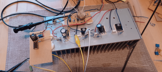
- control loops now seem to work correctly, even under the extreme thermal stress, 40W power loss generates a lot of heat
- offset is now only +11mV while the quiescent current of the control loop actually remains under control, +/-30mAdc around the set 0.8Adc target
- oscilloscope shows a straight horizontal line, no oscillation tendency below a gain of +1.
This is already quite positive and comes pretty close to the first idea of the Eisenport project. Apparently my thread is now mutating into a kind of soap opera - how are the ratings?
^
why not. I didn't even have that in my head - thx.
#
R8,9 are now fixed to 51Ohm, R10,11 fixed 1kOhm ... a few more marginal changes.
Originally, I had not expected the current time required for this development (or the actual tracing of the simulation, the theory).
Now
The temperature,
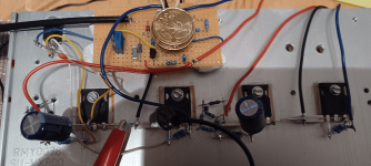
I measure 38°C at the ribs and 48°C as a hotspot directly on the Q1 housing. With the surface area of my beloved test heat sink, I immediately have to think of the current MF-A1, with its tiny convection surface (the lid) and almost 80W power loss, thermal death is still programmed. Whether MF has finally installed a functional signal limiter (two green LEDs would be enough), or still lets the power amplifier drive RAIL to RAIL (until the second breakthrough) ...
does anyone know?
why not. I didn't even have that in my head
- thx.#
R8,9 are now fixed to 51Ohm, R10,11 fixed 1kOhm ... a few more marginal changes.
Originally, I had not expected the current time required for this development (or the actual tracing of the simulation, the theory).
Now
- I have to take my time to think about the real implementation of the reference point / source for the base potential of the BD-140
- that everything is statically in order and the operating point is stable, this strange first simulation result for frequencies greater than or equal to 10kHz is in the back of my mind - this apparent transfer distortion, which theoretically does not fit into the concept at all, especially level and frequency-dependent. It's the little things that always have such an infinitely disruptive effect on motivation.
The temperature,
I measure 38°C at the ribs and 48°C as a hotspot directly on the Q1 housing. With the surface area of my beloved test heat sink, I immediately have to think of the current MF-A1, with its tiny convection surface (the lid) and almost 80W power loss, thermal death is still programmed. Whether MF has finally installed a functional signal limiter (two green LEDs would be enough), or still lets the power amplifier drive RAIL to RAIL (until the second breakthrough) ...
does anyone know?
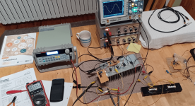
The late night news
Static:
absolutely stable, the new control loop works perfectly, no more fluctuations in the quiescent current - absolutely rock solid now!
Dynamically:
at idle and under load, everything is perfect. The bandwidth under 6 W(rms) modulation is still 900kHz without any frequency response compensation!
Gain:
19.5dB
Comments:
The quiescent current control works perfectly up to input voltages < 1V(rms) and the amplifier remains completely in class A operation. With this controller it makes little sense to exhaust the level range up to 20W (rms) and to checkmate it by switching to Class AB. The clipping starts early on. Rail to rail is of course not possible. 34Vpp is the absolute end, also in terms of operational safety.
Conclusion:
The test fully confirms the theoretical considerations, up to 5W Eisenport can be regarded as a single-ended amplifier, above that as a push-pull amplifier with up to an honest class A 10W.
Summary:
There is no getting around the practical test and proof, the simulation only shows the direction with the HEX-FETs. Tomorrow I will submit the current circuit diagram - and that will be the end of the first season of the soap opera ...
It's time to sleep now,
HBt.
Attachments
Thank you
This is now the provisional end (of season one) of the daily soap opera Eisenport's first act. The set has been tidied up and the little amp has to go back to the prop room.
Normally, the production company now needs two to three years to give birth to a concrete, complete product. But "Haudegen is not on the run", and he may yet meet Dr. Kimble on his journey?!
Attachments
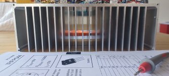
![DSCN0461[1].JPG](/community/data/attachments/1208/1208289-e8d013cd8eea7a74faa4cd14da3824c0.jpg)
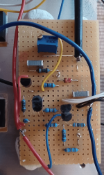
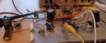
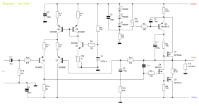
Here is the preliminary final and fully functional circuit that I have been working with over the last few days, building (and evaluating) it step by step.
Of course,
a few obligatory capacitors and a sensible band limitation on the input side are still missing - the balanced input is also not shown, but I leave all that to the reader's imagination.
kind regards,
HBt.
Of course,
a few obligatory capacitors and a sensible band limitation on the input side are still missing - the balanced input is also not shown, but I leave all that to the reader's imagination.
kind regards,
HBt.
Attachments
@cumbb
The first stage is now fully regulated, the offset is just under +11mVdc. Everything else resulted in the open loop case.
The amplifier is extremely fast,
so a band limiter and possibly a soft clipping limiter similar to the NAD devices are advisable.
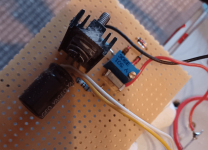
Thanks again for reminding me about the trimmer in the emitter circuit, I had completely forgotten about this classic solution (how embarrassing).
Perhaps a word about the components in general:
I think it's absolutely right, when a product stands, that you stay on the lookout to optimize the sound just by selecting elements that really fit.
This is really exciting and always good for positive surprises.
I'm looking forward to the second season,
HBt.
The first stage is now fully regulated, the offset is just under +11mVdc. Everything else resulted in the open loop case.
The amplifier is extremely fast,
so a band limiter and possibly a soft clipping limiter similar to the NAD devices are advisable.
Thanks again for reminding me about the trimmer in the emitter circuit, I had completely forgotten about this classic solution (how embarrassing).
Perhaps a word about the components in general:
I think it's absolutely right, when a product stands, that you stay on the lookout to optimize the sound just by selecting elements that really fit.
This is really exciting and always good for positive surprises.
I'm looking forward to the second season,
HBt.
second stage (outputside)The first stage is now fully regulated, the offset is just under +11mVdc. Everything else resulted in the open loop case.
emitter circleThe amplifier is extremely fast,
(...)
Thanks again for reminding me about the trimmer in the emitter circuit, I had completely forgotten about this classic solution (how embarrassing).
Sorry for the typo's.
;-)
Nice circuit.
Sounds better than every complex PP, regardless of the price;-)
The BD441/442 are currently among the best-sounding TO-126s, more fluid and real than most others.
If there are TO-220s that can withstand the power, try them. I remember the IRF520N, for example. It sounded a class better than its competitors, and classes better than TO-247s.
BC550/560 are at least upper middle class. Bought and tested a lot from Reichelt. Germany.
The longer I look at the circuit structure, the more potential I recognize. In other words, yes, I fear that tooNice circuit.
Sounds better than every complex PP, regardless of the price ;-)
.We could still use R2 and R4 to establish an electronic fuse and current limiter. A switch-on delay, i.e. an output relay, would also not be a useless luxury.
I also like the design.
Regards,
HBt.
(Would anyone like to make a PCB layout? And share the Gerbers, etc.pp. with everyone?)
Dear Cumbb,The BD441/442 are currently among the best-sounding TO-126s, more fluid and real than most others.
If there are TO-220s that can withstand the power, try them. I remember the IRF520N, for example. It sounded a class better than its competitors, and classes better than TO-247s.
I also have to confirm this to the regret of other users - an experience I share. For decades I relied on the small TIP130/135 & 120/125 as universal Darlingtons. Always with success - but your comment reminds me just of the small Elektor flagship MPA from 1990, where we also find a whole battery of small TOs. BD911 and BD912. The whole thing is crazy, but there must be a physical explanation for it. Likewise the old BC140 /160 with cooling star ...
greetings,
HBt.
It's just a big tragedy with these little plastic cases and especially the fact that the ones currently available don't meet Siemens' original specifications. How could we do away with our own semiconductor manufacturing?BC550/560 are at least upper middle class. Bought and tested a lot from Reichelt. Germany.
Once bought a lot of TO-92 from Reichelt for testing. 3 pieces each. Including KSP44. They sounded great, had an extreme character, in German: "Schlagwerk" (not "Schlagzeug"-) Then I immediately ordered 20 or 30 more. They were then inconsequential, mediocre. Another batch. Now I have three awesome KSP44s, but I don't have a project yet;-)
An example;-)
- Home
- Amplifiers
- Solid State
- Eisenport - Three ideas in class A operation