This Point
#
Spontaneous oscillation and microphonic effects or even the familiar singing of some components, even in the LF range, are among the points that come to mind. Thank God, many phenomena can be demonstrated using measurements and can be plausibly explained in connection with auditory sensations.
But correlation is not automatically the cause.
")
Regards,
HBt.
is totally undisputed.of course its inductance is making the circuit oscillate, or its Johnson noise is high enough.
#
Spontaneous oscillation and microphonic effects or even the familiar singing of some components, even in the LF range, are among the points that come to mind. Thank God, many phenomena can be demonstrated using measurements and can be plausibly explained in connection with auditory sensations.
But correlation is not automatically the cause.
Regards,
HBt.
Last edited:
There was a dispute between Ethan W. and Paul McG. some times ago.
And this discourse spontaneously came into my mind when I read the distortion spectrum (compare it with the Eisenport-Simulations) with /of some German publication on the current infusion of the MF-A1.
According to Ethan's statement (which I highly respect), both black boxes would now be the same /equal, but they are absolutely not the same. And when Paul (who I also appreciate) says, if an auditory difference (hopefully clearly reproducible) is heard, then there must also be a difference (unspecified), completely independent of the identical measurement results.
The difference is that the circuits are not identical; they set and process their signals and tasks in different ways.
When viewed as a black box, they perform the identical task.
If a zero or null test/er now shows no clearly audible result, the constructive difference remains, but the task is viewed as the same as a result.
I like to differentiate between hearing measurement methods and visual measurement methods. In the audio field, when it comes to hearing, I prefer hearing measurement methods;-)
... particularly as the hearing and listening measurement methods are hardly "calibrated" to each other;-)
By the way: A simple experiment: buy 20 different components, e.g. transistors or resistors, compare them using the listening-measuring method: only 10%: 2 pcs., will be suitable for audio;-) A discussion about circuits then takes on another quality: if components modulate audibly, do complex circuits or half-wave separated amplifiers sound... ehmmm...-?
A simple test regarding the material issue is quite easy to carry out.
Two identical JHLs are compared with each other, one of them contains the "bad" resistors and the other the "good" resistors. Both are listened to knowingly, i.e. identified -> as well as the remaining output signal of the zero /null tester. If you hear a clear difference here, then there is one. Now comes the decisive round, the double-blind test, combined with the question: can the audience identify the amplifier with the "good" resistors with statistically 100% certainty?
#
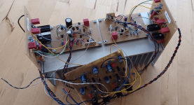
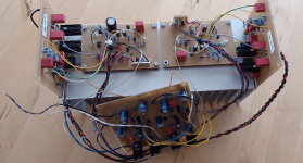
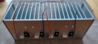
I'm attaching a picture of my usual test setups, I'll get started right away with this heatsink.
Two identical JHLs are compared with each other, one of them contains the "bad" resistors and the other the "good" resistors. Both are listened to knowingly, i.e. identified -> as well as the remaining output signal of the zero /null tester. If you hear a clear difference here, then there is one. Now comes the decisive round, the double-blind test, combined with the question: can the audience identify the amplifier with the "good" resistors with statistically 100% certainty?
#
I'm attaching a picture of my usual test setups, I'll get started right away with this heatsink.
Attachments
I would even use just one JLH, i.e. a pair. Because even identical amplifiers have different "noise behavior". It is also advisable to take a break between listening sessions, as experience has shown that our hearing needs some time to process, mentally compare and memorize something.
Blind testing is only apparently scientific. At best, I would ask several listeners to take notes. If they come up with roughly the same statements, then that would enough confirmation for me;-)
Blind testing is only apparently scientific. At best, I would ask several listeners to take notes. If they come up with roughly the same statements, then that would enough confirmation for me;-)
I don't really want to fuel the discussion, but I've just thought of something that fits the bill:
We all know the preamplifier inside the old, original MF-A1, and it was precisely this (i.e. adder plus inverting op-amp with potentiometer in the negative feedback) that I once married to a small SYMM over thirty years ago. An integrated amplifier as a Christmas present. Later, I listened passionately to music for a long time with this very construct, the Grim Reaper had visited the recipient and I now tanned the amplifier.
I lowered the gain factor of the PRE and at some point spontaneously decided to replace the usual ALPS with the new wonders from Panasonic, the conductive plastic potentiometer with the four connections.
The difference in sound was striking, very clear, positive, almost a new dimension - positively different, somehow more natural in the sense of naturalness.
I still own one of these wonders, untouched for decades.
Something perhaps irrelevant to the final concept but struck me: what is the motivation for the LTP current source in amp 1? Or stated another way, is there a benefit to this arrangement vs a more conventional single transistor output current source? Given the shorting of LTP emitters, I see current source RO cut in half, but I have not analyzed in detail.
Facepalm! Get real...The ear perceives differences, which it reconstructs into frequencies, into music. What is modulated by material on a micro level is audibly represented on a cubic meter scale: components modulate the signal audibly considerably,
A comparable example are musical instruments: such as the body and strings, or teeth and skull. Teeth vibrate, resonate, (frequencies) which has a considerable effect on the entire organism via the electrical network (nervous system). If you have teeth extracted, you may have to have the opposite half of the body (two halves of the body, equal to stereo, or even two-half-waves-amplification) extracted as well, otherwise the entire organism will be thrown into chaos, even to the point of collapse. In the case of teeth - or two-half-wave amplifiers, symmetry is the key;-)
A beginner's exercise for you, Mark: place your amplifier on different materials (wood, metal, stone, glass, rubber...) and listen;-)
With double-blind testing, assumed correlations are no longer heard. But if a suggestion is made that the difference between two amplifiers must inevitably be heard (e.g. a tube and a solid state), then that is heard. Even if only one amplifier is actually being tested...
Say that the lie is immediately recognized by someone, and it is agreed. Say that the truth is immediately recognized by someone, and it is agreed.
In general, the posted designs by the op are interesting, but not a breakthrough. One can recognize chunks from other circuits, also valid, and these mixups tend to behave well once build. But is there an ultimate design? Hence my 'free rein' remarks in #20.
It is only since a few years that I can hear differences between brands of classical piano's, but not good enough to determine that actual brand. I'm not a musician. That's in a distance of nearly fourty years.
As an electronic engineer, I aquired some preferences about recordings and source media (10%), amplification (precise: 10%, 'natural' 20%), and the loudspeaker (magnetic: 80%, planar 90%).
Being at the solid state amplifier platform, avoiding troublesome approaches seemes to yield in the best subjective (!) audiable and reality comparable performances so far.
Ok, I neglected the halving of RE when you change from two to one transistors so the output impedances are the same at LF... But capacitances are doubled so by 20k the output impedance is halved with two transistors.Something perhaps irrelevant to the final concept but struck me: what is the motivation for the LTP current source in amp 1? Or stated another way, is there a benefit to this arrangement vs a more conventional single transistor output current source? Given the shorting of LTP emitters, I see current source RO cut in half, but I have not analyzed in detail.
@dkfan9,
the simplest partial answer to your question is to reduce the power loss. But since the individual emitter resistor is now correspondingly larger, the individual source or sink is also closer to the ideal than with a low-impedance, very small resistor in the emitter circuit.
In the real experiment I did without this, and the current mirror is kept quite classic and very simple, but the small transistors now get very hot in their plastic housing and their power dissipation is already approaching the operating limits.
So everything revolves around the power dissipation of the components and the quality of the local control loop.
Attachments
Of course, all existing audio amplifiers are ultimately based on basic circuits or models, that is quite clear. You won't be able to find anything new.
The first thing on the agenda is the reliable function, while the motivation can also clearly be a very specific component (alone) the cause of a design.
If you /we are looking for the ultimate concept or even the specific circuit itself, then you /we will definitely end up searching in vain (for the holy grail).
The little soup pot "iron port" is no exception to this rule.
But Citizen124032,
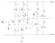
I would be very happy to receive a concrete circuit suggestion from you. The design framework is fixed: +/-20Vdc, two-stage, N-MOSFET output stage in A -> AB mode.
Perhaps we can achieve a breakthrough together.
The first thing on the agenda is the reliable function, while the motivation can also clearly be a very specific component (alone) the cause of a design.
If you /we are looking for the ultimate concept or even the specific circuit itself, then you /we will definitely end up searching in vain (for the holy grail).
The little soup pot "iron port" is no exception to this rule.
But Citizen124032,
I would be very happy to receive a concrete circuit suggestion from you. The design framework is fixed: +/-20Vdc, two-stage, N-MOSFET output stage in A -> AB mode.
Perhaps we can achieve a breakthrough together.
That's true Mark,The electrons don't care what you put the amplifier on, just physics...
but I'm personally interested in the platform on which the little electrons cavort and the little charging men transport loads.
It doesn't just look better on granite or marble ...
Material vibrations or vibrations definitely disturb my well-being - and let's remember why evolution gave us hearing/our senses.
Incidentally, the electron is not indifferent to physics either - after all, what is an electron? But please don't say a negatively charged elementary particle, ok?
friendly,
HBt.
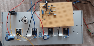
An interim result:
The last, concrete idea does not work statically within the limits predicted by the simulation. Quiescent currents up to just under 0.4A can be set well and stably with Rx, but then at some point things start to go wrong.
However, the single-stage variant with a voltage divider from the output to the input of the Q3 already works quite well, division 7k & 3k. A local current-voltage negative feedback is able to set the desired operating point within wide limits. The thermal drift is even acceptable with the current size of the heat sink.
UGS_044 currently <3.5V
UGS_510 currently <3.1V
Quiescent current approx. 0.8A
However, the output offset is <3V, there is still so much to do before such a construct really works.
Attachments

Now some questions arise, do we need a gate series resistor in each case? Gate stopper. And if so, in what order of magnitude? Protection diodes, does the design require Z diodes? Above all, how do we ensure a DC-free output?
#
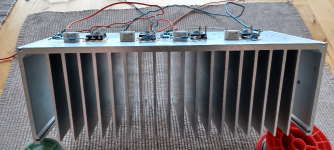
The power dissipation per channel is already just under 40W, i.e. the heat sink dimensions shown in the picture are just sufficient for one branch. To avoid a thermal disaster.
#
The power dissipation per channel is already just under 40W, i.e. the heat sink dimensions shown in the picture are just sufficient for one branch. To avoid a thermal disaster.
It may make sense to use smaller power transistors (TO-220) and reduce the power dissipation. The sound will still be cleaner, more contoured and clearer. It is due to the disregard of "current" in the construction of transistors.
By the way: The mechanical damping of the cooling fins will also be audible. It is also possible to influence the tonal tuning here.
By the way: The mechanical damping of the cooling fins will also be audible. It is also possible to influence the tonal tuning here.
In the meantime, of course, I continue to work diligently on the small development, actually on the object.
Regardless of the second stage -
which is perfectly functional on its own, see also the PLH litter (but with at least three trimming potentiometers - that alone speaks for itself and the specimen scattering), with appropriate cooling. The Q3 in particular must remain cool in relation to its surroundings under all circumstances. It needs its own heat sink.
To ensure a DC-free output (and two-stage-amp /testing), I always couple the first stage with the second stage, with and without feedback.
Q6 gets really hot, which is not surprising given its power dissipation of >0.3W; it should be thermally coupled with Q5. In other words, physically lash it together. To be honest, 23mA is also a bit too much of a good thing. Either double R7 and halve the current, or split it up - so that Q6 remains cold under all circumstances.
But having the offset set automatically is not a good idea, because at some point the ensemble will tip over - guaranteed.
Last edited:
According to the motto "giving up is not an option", reflection is required.
First of all, the current mirror must work better and the power losses, i.e. the temperatures, must fall. Q6 and Q8 must be thermally coupled with each other and R7 can be (theoretically) up to 10kOhm as the R-Gate of Q3, it does not necessarily have to be low impedance. 2 times 3mA should fit much better and this inevitably results from RF||RN approx. 2kOhm, from the test of the output stage as a single stage alone.
Let's see.
Attachments
- Home
- Amplifiers
- Solid State
- Eisenport - Three ideas in class A operation