Hmm, don’t know if it worth the effort either, isn’t a SRPP not a rudimentary form of a Mu follower? The input impedance at the cathode of a Mu follower is high (app Ra/µ). So there is almost no current to drive for the cathode follower. This means basically that the cathode follower as well as the Mu follower can operate almost distortionless in open loop. Any realistic resistance to set bias current at the cathodes will rise distortion (for the cathode follower). So a CCS at the cathodes is not a bad idea.
Although it looks like a LTP, I wouldn’t consider the circuit as such. Merely a grounded grid stage driven by a cathode follower, although curvature (distortion) cancellation occurs.
Cheers")
Although it looks like a LTP, I wouldn’t consider the circuit as such. Merely a grounded grid stage driven by a cathode follower, although curvature (distortion) cancellation occurs.
Cheers
Hi,
Sure is.
I don't know if anyone actually tried this configuration (sim or built) with the mu-follower iso the srrp.
It would be interesting to see how it does.
Looks like an LTP from afar, I agree.
Cheers,
isn’t a SRPP not a rudimentary form of a Mu follower?
Sure is.
I don't know if anyone actually tried this configuration (sim or built) with the mu-follower iso the srrp.
It would be interesting to see how it does.
Although it looks like a LTP, I wouldn’t consider the circuit as such. Merely a grounded grid stage driven by a cathode follower, although curvature (distortion) cancellation occurs.
Looks like an LTP from afar, I agree.
Cheers,
This topology is in the same family of differential amp as the LTP, except, as you note, for the plate bypass cap on the input triode. This pins the plate voltage of the input stage and makes it work like a follower instead of an amplifier.
If the SRPP upper triode is replaced with a resistor, then my term for this amp is a common cathode stage (not everyone uses this term).
I like this topology because of the opportunity for NFB. I don't think that most preamps need the gain of 20-30 that comes with grounded cathode stages. With a modest amount of NFB you can reduce the gain to something more reasonable and reduce the Zo and THD too. It is easy to play with these resistor values after the amp is built. Or even to replace the voltage divider with a pot, at least for experimentation.
I know that many DIYers here don't like NFB, so this is not for everyone.
Still, gentlemen, I would really like to see someone build this and try it out. It has a good reputation when it appears in commercial preamps.
Hi,
When I started the circuit it was actually not for a pre amp but for a buffer amp for an active tube x-over. For that I need very low output impedance (< 1 ohm) up to high frequencies. I build many buffer amps according to this topology in SS as video buffers for studio distribution amps, so why not with tubes for audio
Up to now I have only a bunch of PSpice simulations but not actually build the thing. It shows that with the very high impedance involved with a Mu-follower, parasitic capacitance can play havoc.
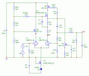
Attached the simulation schematic. Warning: It is not actually build and tested up to now. I put it up for discussion only!
Cheers
When I started the circuit it was actually not for a pre amp but for a buffer amp for an active tube x-over. For that I need very low output impedance (< 1 ohm) up to high frequencies. I build many buffer amps according to this topology in SS as video buffers for studio distribution amps, so why not with tubes for audio
Up to now I have only a bunch of PSpice simulations but not actually build the thing. It shows that with the very high impedance involved with a Mu-follower, parasitic capacitance can play havoc.
Attached the simulation schematic. Warning: It is not actually build and tested up to now. I put it up for discussion only!
Cheers
Attachments
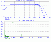
And here some simulation results. I’ve used Norman Kooren’s model for a 12BH7, which is not far off an ECC99 (lower mu). Frequency plot is for a cable load of 100pf to 1nF and a load resistance of 47K. Intermodulation shows products well below 120 dB (FWIW of course).
Attachments
Hello Pjotr. Here is an ECC99 model for you. It is a pspice model not a berkely model. so it should work.
*
* Triode Model for ECC99
*
* Alex Cavalli
* 2003
*
* Based on models from Norman Koren
*
* Grid current is modeled with a diode.
*
* Please note that this model is provided "as is" and
* no warranty is provided in respect of its suitability
* for any application.
*
* This model is provided for educational and non-profit use.
*
.SUBCKT ECC99 1 2 3
E1 7 0 VALUE=
+{V(1,3)/500*LOG(1+EXP(500*(1/22+V(2,3)/SQRT(300+V(1,3)*V(1,3)))))}
G1 1 3 VALUE={(PWR(V(7),1.3)+PWRS(V(7),1.3))/362}
RCP 1 3 1G ; TO AVOID FLOATING NODES IN MU-FOLLOWER
C1 2 3 5.8p
C2 2 1 5.1p
C3 1 3 0.91p
D3 5 3 DX ; FOR GRID CURRENT
R1 2 5 2000 ; FOR GRID CURRENT
.MODEL DX D(IS=1N RS=1 CJO=0 TT=1N)
.ENDS
*
* Triode Model for ECC99
*
* Alex Cavalli
* 2003
*
* Based on models from Norman Koren
*
* Grid current is modeled with a diode.
*
* Please note that this model is provided "as is" and
* no warranty is provided in respect of its suitability
* for any application.
*
* This model is provided for educational and non-profit use.
*
.SUBCKT ECC99 1 2 3
E1 7 0 VALUE=
+{V(1,3)/500*LOG(1+EXP(500*(1/22+V(2,3)/SQRT(300+V(1,3)*V(1,3)))))}
G1 1 3 VALUE={(PWR(V(7),1.3)+PWRS(V(7),1.3))/362}
RCP 1 3 1G ; TO AVOID FLOATING NODES IN MU-FOLLOWER
C1 2 3 5.8p
C2 2 1 5.1p
C3 1 3 0.91p
D3 5 3 DX ; FOR GRID CURRENT
R1 2 5 2000 ; FOR GRID CURRENT
.MODEL DX D(IS=1N RS=1 CJO=0 TT=1N)
.ENDS
That I generally agree with, but maybe he tried it and didn't like it. Not all source components are going to thank you for being loaded down by that sort of design. The later designs use S&B transformers.billr said:I notice that the raven preamp has a stereo volume control per channel. this is just crappy design.
A single pot wired across the phase and antiphase lines, with the wiper taken to one side is all that is required.
There I disagree stongly. A simple two stage will 'work', but the design shown provides real improvements in the downward dynamic range. I was a real sceptic until I tried it and I'm waaaay to lazy to build something complex when something simple will do..the PSU is also a bit on the complex side for a simple class A amp. As the current take is relatively light, a simple two stage RC coupled PSU filter is all that is required.
Ehm Runeight,
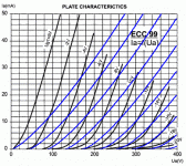
Don’t know, the simulated curves according to the model are not much in agreement with the published curves for the region of interest (2 mA – 10 mA). Attached an overlay of the published curves of the ECC99 and the curves of the model (in blue). Slightly off is normal, but that much? Where did you found them Runeight?
Cheers
Attachments
Hi,
Not Runeight but those curves are what JJ themselves published for the ECC99 datasheet.
Cheers,
Where did you found them Runeight?
Not Runeight but those curves are what JJ themselves published for the ECC99 datasheet.
Cheers,
fdegrove said:Not Runeight but those curves are what JJ themselves published for the ECC99 datasheet.
Cheers,
Ehm yes Frank, I know and that is what I used. But the blue curves are the model of post 27.
Cheers
Say, pjotr, i am wondering if you made some mistake when generating the model plots.
i just plotted mine out from the model i sent you and the model is very close to the published curves.
don't know where the problem might be, but at this moment i think the model is correct.
let me know . . .
i just plotted mine out from the model i sent you and the model is very close to the published curves.
don't know where the problem might be, but at this moment i think the model is correct.
let me know . . .
Thanks for those curves Runeight,
OrCad uses "LOG(z)" for the natural logarithm (log_e) and "LOG10(z)" for the common logarithm (log_10). However in Microcap7 that I use, "LOG(z)" is used for the common logarithm and "LN(z)" is used for the natural logarithm. So changing “LOG” in the posted model into “LN” fixed the problem.
Cheers
OrCad uses "LOG(z)" for the natural logarithm (log_e) and "LOG10(z)" for the common logarithm (log_10). However in Microcap7 that I use, "LOG(z)" is used for the common logarithm and "LN(z)" is used for the natural logarithm. So changing “LOG” in the posted model into “LN” fixed the problem.
Cheers
- Status
- This old topic is closed. If you want to reopen this topic, contact a moderator using the "Report Post" button.
- Home
- Amplifiers
- Tubes / Valves
- ECC99 line preamp