Yes I'll try that. I'll pick up a bottle of the 'stuff' soon.
If peroxide can bleach skin pigments ( I'm brown ...will tell easily !) then this one may not be it as it didn't bleach my skin or leave any marks. Just felt like a burning sensation when it touched the skin until washed off with water.
I have some 10% H202 here but that's too dilute to bleach skin pigments!
Did it feel soapy on your skin?
For the others, once an enamel is set and cured, a solvent won't affect it much. You can only corrode it off.
Hi SySolvent won't do it- the enamel is a thermoset. You're stuck with abrasion or scraping. Sorry.
You are right.
With patience, I burned the enamel with a cigarette lighter, then sanded with steel wool, so I could solder.

Try soaking in acetone tips of wires overnight, put them between lid and neck of smal bottle. I disassembled such a way HF transformers, after 2 days in can with acetone epoxy is softer and breaks easily.
Also, fine sand paper helps. Bend it twice, put wires between, squeeze by finger tips and pull jently.
Also, fine sand paper helps. Bend it twice, put wires between, squeeze by finger tips and pull jently.

Hi Tony
Already tried a cutter, only serves to thick wires, remove too much copper.
i use them for coppers from gage 8 to 32, from 32 down to 38 i merely scratch the copper, enough to solder them unto tags or pigtails....
the thicker wires, 20 and up need more working....
Back to the topic, maybe.
Not to step on toes sometimes the “best” most linier out of the NOS box triode is the best pick. Then we add the best Solid State Constant Current Source or Mu follower to draw straight load lines across the assumed grid curves. The effort here is to design the best possible stand alone device, say an riaa equalization pre-amplifier.
Now to question the assumptions regarding a one size fits all triode distortion test jig. The Morgan Jones medium mu test method produces valid results for a restricted set of assumptions and conditions. If the tube has a chance at 8 milliamps it may test well. If the circuit you are building does not operate at a constant 8ma your results may vary.
I play with this stuff because I like tweaking the old technology and adjusting my understanding of what I know. (Adjusting my assumptions and the assumption of others) I also like the old musty texts with graphics and calculus.
I like this old musty article George Fletcher Cooper.
http://tubecad.com/2005/March/02/Which Tube Shall I Use.pdf
The performance of the tube depends on the circuit that supports it. An example of this is parameter restriction by the use of a Constant Current Source. Another example is the 180 degree out of phase series triodes like in the SRPP circuit in this thread. George Cooper points out that to minimize a pentode or triode distortion select a tube with a ruler straight graph of grid voltage to transconductance, or to select an operational point in the center straight portion of that curve. Then George points out that the addition of a cathode resistor with change curve rate of the graph of grid voltage to transconductance and the total content of 3rd harmonic. The selection of the correct cathode resistor and grid voltage will minimize the 3rd harmonic. This was news to me when I read it. For grins I put this in the simulator with my favorite triode at the time. It was interesting to observe the 3rd harmonic and higher nearly disappear with the adjustment of the cathode resistor and or putting a resistor in series with a cathode resistor bypass capacitor. Not much happened to the 2nd harmonic with the adjustment of the cathode resistor. Putting two triodes in series (SRPP) reduced the second harmonic, selection of the cathode resistors and B+ voltage to set the grid voltage and plate current reduced the 3rd and higher harmonics.
From the point of view of tweaking a tube and support circuit for optimum performance the 12AU7 is a perfect tube to play with. A perfect tube has less to play with. I do think that there is an electron cloud in there as well.
DT
Hi DualTriode
I agree with you on what you say, a perfect tube has less to play with, and of course there is an electron cloud in there. (I do not want to talk about it)
Very good article and very good your approach.
Unfortunately, almost no datasheets are achieved with gm vs Vg curves, so making implementation difficult, as with traditional methods, plus the fact that in the real world, valves are different from what the datasheet says, there is not a huge difference compared to simulations, so the only way is to test and measure.
I can not make many measurements, just this year gave me an old scope, now it makes sense to build a signal generator.
With all that against me, simulations make much sense, also needed a rule of thumb, mine is working with the highest allowed +B and remain below dissipation limit curve, you already know the reason, that was the subject of much debate.
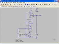
A line preamp is not a difficult matter, almost any bus leaves at home.
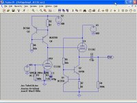
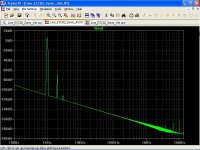
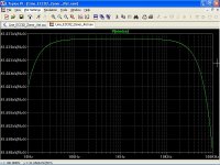
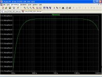
I think this brings interesting features, low distortion (0.04%), low noise, and output impedance in the order of 500 ohm.
The high voltage is a minor detail.
I think this brings interesting features, low distortion (0.04%), low noise, and output impedance in the order of 500 ohm.
The high voltage is a minor detail.
Attachments
Hi Dady
Nice to see you around here.
In view of the results obtained, I consider seriously this valve for my future designs.
Note that the circuit in post #172, #173, Vout = 6 Vpp, more than enough to drive most power amps IMHO.
If you use a more linear valve, the results must be better ?
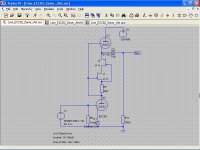
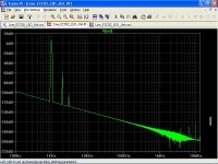
I have eight NOS RCA 5687, so I made sims for it, the result was disappointing.
In the noise department, the 5687 is a winner because its high transconductance, however you can't go crazy with +B, Vkf = 100 V, distortion was acceptable.
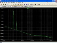
An innocent potentiometer, can ruin your day !
When inserted the volume pot, all rotted, ofcourse noise, and especially the phase shift at high frequency.
A look at the datasheets clarify the situation
http://www.drtube.com/datasheets/ecc82-philips1969.pdf
http://www.drtube.com/datasheets/5687-ge1959.pdf
It's just my impression or interelectrode capacitances of ECC82/12AU7 are amazingly low ?
Maybe also consistently bad from sample to sample ?
Nice to see you around here.
In view of the results obtained, I consider seriously this valve for my future designs.
Note that the circuit in post #172, #173, Vout = 6 Vpp, more than enough to drive most power amps IMHO.
If you use a more linear valve, the results must be better ?
I have eight NOS RCA 5687, so I made sims for it, the result was disappointing.
In the noise department, the 5687 is a winner because its high transconductance, however you can't go crazy with +B, Vkf = 100 V, distortion was acceptable.
An innocent potentiometer, can ruin your day !
When inserted the volume pot, all rotted, ofcourse noise, and especially the phase shift at high frequency.
A look at the datasheets clarify the situation
http://www.drtube.com/datasheets/ecc82-philips1969.pdf
http://www.drtube.com/datasheets/5687-ge1959.pdf
It's just my impression or interelectrode capacitances of ECC82/12AU7 are amazingly low ?
Maybe also consistently bad from sample to sample ?
Maybe also consistently bad from sample to sample ?
Some have less audible distortion. Please tell us what 12AU7's you were using.
jeff
Maybe also consistently bad from sample to sample ?
It's just an irony about what someone said
sic "Later generation valves such as the ECC82 (also intented for use as a field scan oscillator) benefited from improved production techniques and distortion is extremely consistent from sample to sample: it is consistently poor."
Some have less audible distortion. Please tell us what 12AU7's you were using.
As rightly points Dady, is just a simulation.
For those interested in simulations, they are made based on the mathematical model from Norman Koren, which in turn uses the curves of Mullard ECC82.
I have only some NOS Miniwatt, Tungsram...
A 2SK170 cascoding another 2SK170, is there enough Vds for the bottom one? In cascoding general the top common gate one should provide at least 2x Vgs(off) than the bottom common source one.
Hi Salas
You honor me with your visit.
I totally agree with what you say, I also drew attention about that.
Probably the mathematical model that I have for 2SK170 is wrong.
Maybe RdsOn can help?
Toshiba does not mention RdsOn in its datasheet.
Putting a resistror, as in the previous circuit, the current is reduced too much, not to mention noise effects.
Possibly I'm saying nonsense, but remember that I'm just a TV repairman.
Last edited:
- Status
- This old topic is closed. If you want to reopen this topic, contact a moderator using the "Report Post" button.
- Home
- Member Areas
- The Lounge
- ECC82/12AU7 Line Preamp