Zobel's rely on you researching, measuring and drawing an impedance vs frequency curve (resistor, scope + App for generating the tones + graph paper).
The result is well worth it as class D really only has a flat FR into a stable impedance.
I had your 2ohm 7498 design myself. I modded it - removed all caps, coils and the resistors and replaced the coils with 4 air cores of 10uH and 4 220nF capacitors.
Note you can also raise the frequency although it was a bit fiddly and reduce the huge gain. It may be easier to buy a new one - the one you show in your last post looked good to me too. Switchable gain is good - far easier than solder SMD for me.
As also noted improve the supply caps. With my new filter it had a nice sound but like all class-D it's quite speaker dependant although my simulations suggested to me that my filter values (10uH into 220nF) gave the best compromise with a 4,8,16 ohm range.
Your mileage may vary.
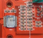
Happend to receive the one with the big white resistors on the output finally (mine has red PCB instead of black).
I want to reduce the gain to the lowest setting. How do I do this?
Pin Gain0 seems to be connected to 1,5V, Gain1 seems to be unconnected. (see attachment).
Do both need to be unconnected? Or do I need to short Gain1 with Gain0?
Attachments
What can kill a TDA7498?
I am hoping there may be some experience among the forum members relating to a problem I'm experiencing with some TDA7498 amps I acquired for a small party-system project. They sound great and work well. The problem is that when I turn the system off and back on, frequently one of the amps no longer works. The amps that are failing are always the attached subs. The system has a 3-way active x-over in the top unit which has the tweeter and mid driver in it along with the amp for them, and puts out a balanced signal to the subs. There is 250Ω on each output line and a 1k resistor between hot and cold at each amp - this means that whether 1, 2 or 3 subs are attached the balance of the 3-way system stays pretty much the same.
Each sub amp has 2 8Ω drivers attached to it's 2 outputs. There is an XLR connector from the top unit carrying both balanced signal and power to each sub amp, 3 subs per side. After the first 3 amps died I put measures to keep the input pins of the chip between -0.3V and +3.3V, but this has not stopped amps from dying. Amps die whether I'm switching the entire system or plugging individual subs into already powered top units.
I'm wondering, can anyone think of anything else that can kill these chips during power ramp-up/down other than wild input signals?
The boards are the basic cheap black one with the 5W resistor on the output with a few mods:

The PSU is a 1500W DC-DC boost set at 32V, running from the 24V solar batteries that run my house. I'm considering putting an additional 22000uF cap in each top unit to carry the beat, and I intend to push the voltage up to 39V once the amps stop dying.
Hoping that someone out there has some experience and ideas... Thankyou
I am hoping there may be some experience among the forum members relating to a problem I'm experiencing with some TDA7498 amps I acquired for a small party-system project. They sound great and work well. The problem is that when I turn the system off and back on, frequently one of the amps no longer works. The amps that are failing are always the attached subs. The system has a 3-way active x-over in the top unit which has the tweeter and mid driver in it along with the amp for them, and puts out a balanced signal to the subs. There is 250Ω on each output line and a 1k resistor between hot and cold at each amp - this means that whether 1, 2 or 3 subs are attached the balance of the 3-way system stays pretty much the same.
Each sub amp has 2 8Ω drivers attached to it's 2 outputs. There is an XLR connector from the top unit carrying both balanced signal and power to each sub amp, 3 subs per side. After the first 3 amps died I put measures to keep the input pins of the chip between -0.3V and +3.3V, but this has not stopped amps from dying. Amps die whether I'm switching the entire system or plugging individual subs into already powered top units.
I'm wondering, can anyone think of anything else that can kill these chips during power ramp-up/down other than wild input signals?
The boards are the basic cheap black one with the 5W resistor on the output with a few mods:
- power cap -> 50V 2200uF Nichicon PJ
- removal of power jack to solder power wire connector
- removal of input plug
- removal of gain pot
- removal of 1uF->gnd cap's from originally unused -ve inputs, and cross-connecting them to the opposite +ve input. This makes the two inputs hot and cold and the two amps then amplify the balanced input oppositely, meaning that the incorrect labelling of the output polarity becomes correct. I kept the 470nF input caps since I didn't think that a rolloff at 11Hz would be a problem.
- connecting 0-3.3V protection circuit to chip side of input caps.
- slight mod to 3.3V supply to enable it to supply the protection circuit.
The PSU is a 1500W DC-DC boost set at 32V, running from the 24V solar batteries that run my house. I'm considering putting an additional 22000uF cap in each top unit to carry the beat, and I intend to push the voltage up to 39V once the amps stop dying.
Hoping that someone out there has some experience and ideas... Thankyou
I always look at the datasheets before I buy anything ... the only thought I could find in there was the inputs going outside their range of -0.3v to +3.6v due to the power capacitor inrush offsetting 0V on the sub amp relative to the active x-over.
a rough connection diagram is attached, to try to make things clear.
since asking my original question I looked again at my XLR's and decided that the shield connection was not good enough - just a side pressure contact made with a bendy metal fiinger - so I've added a small screw to ensure the 0V connection isn't the highest resistance of the 4.
I'm also now (working on the inrush assumption) making a dv/dt controlled power-up with a p-channel MOSFET (IRF4905) on the +ve rail. The one remaining sub amp has survived 20 power-ups now with this attached, though now it mysteriously goes quiet after about 10 minutes - a condition which resets only if the power is cycled again. Any thoughts on this one? I think it needs to latch on when it reaches the +ve rail so the main capacitor can recharge at full speed while in use. I'll add power-ramp muting to it too, since there is sometimes noise which sounds like oscillation in the amp while the FET is controlling the power-up.
I'm still interested to hear from anyone having reliability issues with these chips at turn-on...
Attachments
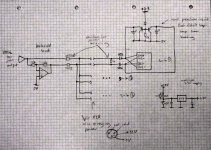
Is this drawing suggesting the use of the same XLR for power and signal? That would need more than just the clamps: series resistors for limiting current through the clamps.
series resistors where? before or after the DC blocking capacitors? why? surely the current into the clamps is limited by the relative dv/dt of the signal wires to 0V and the capacitance of the blocking capacitors... oh wait, now that I calculate it the 100mA hold-down from the BC556's is maxed out by just 0.2V/µs... so to limit a 39V instantaneous jump to 100mA needs just 390Ω, I guess I can fit that in there without loosing signal
I put the power and signal on the same connector because I've had problems with noise from running separate 0V connections for power and signal in the past, and it seemed like a neat solution to use the shield of the signal cable for the 0V power as well. +V is then a separate wire bound to the outside of the signal cable.
the dv/dt limited power-up has stopped the massive voltage step issue, and makes pluging in quiet and spark-free but now I have another problem, that this amp cuts out after a few minutes (not volume related). it might be thermal since it takes less time to cut out if it's already done it once and I'm starting to suspect the LM1117-3.3 regulator ... perhaps I should start again with a new amp board and see if the problem is still there...
Since input impedance of this IC is about 60kohm, a higher value of protection resistor will not degrade audio and will result in less current across clamping elements, like 1k for ~40mA peak.
I recommend a 4 or 5 pin XLR unless you have 3 pin surplus parts to expend.
Thankyou, Eva, you've given me exactly the nudge I needed!
My brain was stuck because I couldn't understand why the clamps hadn't worked and so thought that some other fail point must be responsible.
Actually the inputs are 30kΩ because they're paralleled. I've used 510Ω inline with each capacitor and everything seems to be fine now, though now that I think about it, as long as I do the same to every amp I can put whatever resistance I like in there and just boost it at the x-over input (which has variable gain already) if needed (which probably not, since the level will go up by 30% already when I remove the 2.2Ω resistors).
I've been repeatedly cycling the power both hot-plugging and whole system and it all still works. Now I just need to wait for the IRF4905's I ordered to arrive - even if they aren't needed any more for the amps safety I like that the dv/dt controlled startup means no clicks/pops/sparks or oxidised contacts in the system.
If I'd known 4-pin XLR's existed when I ordered the parts I would have probably ordered them
(although the supplier I ordered most things from doesn't have them, so maybe not)the other little problem I had with the amp shutting down after a few minutes was the LM1117 shutting off after a while because it's input voltage was too high. The glass 12V zener in the PSU mod had got cracked by pressure from the heatsink. Replaced and all is perfect
There's still a lot of work to be done before I can properly test this 1200W 'outdoor hifi', but now I know I will have it working soon enough - maybe even ready for my birthday...
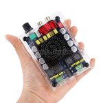
I see on post #256 that a raspberry pi acrylic case can be made to hold the Sanwu TDA7498. But there is a case that is being made for the Nobsound TDA7498, which I have attached a pic for, but I cannot find this case as a separate purchase. Anyone have luck finding it?
Also, if you are up for getting a genuine Sanwu board, they are available very competitively directly from them at www.sanwulasers.org. The basic TDA7498 with no volume knob is $11 shipped at the moment with the RCA and volume knob version coming in at $12.
Also, if you are up for getting a genuine Sanwu board, they are available very competitively directly from them at www.sanwulasers.org. The basic TDA7498 with no volume knob is $11 shipped at the moment with the RCA and volume knob version coming in at $12.
Attachments
I'm facing a persistent buzzing problem with the tda7498 board. The board was quite out of the box but once I removed the dual channel volume pot to solder extension wires between them for installation in chassis, I noticed a buzzing sound. It took me weeks to figure out that the extension wires between the pot were the problem.
I have tried grounding(earth) the pots outer shell(direct croc clips) but it does not solve the buzzing issue.
This board does not have a ground(earth) lead anywhere on the board. The four screw holes on the board connect to nothing and attaching a ground lead to any one of those holes does nothing.
The only solution now is to desolder the extension wires and put the pot back on the PCB.
If anyone has any solution or advise to rectify this issue, please share
Update: Problem solved
Since the tda7498 doesn't have a grounds input lead nor are it's screw hole pads connected to anything, the solution is to take the ground(earth) wire and connect to the 0v input rail. This makes the amp quiet again.
In my case, I soldered a small wire to the 0v leg of the volume pot and connected the other end to the chassis screw near it; my chassis is grounded at the mains input source itself.
So if anyone else is getting a buzz/humming sound after extending the volume pot near the front panel, make sure to join 0v+ground(earth) leads together on the tda7498 amp.
Extra note: the sealed 50k volume pot's outer metal case is isolated and not conected to anything inside. So connecting the ground(earth) wire to this case did not remove the hum hence leading me to believe that my unit was defective.
I see on post #256 that a raspberry pi acrylic case can be made to hold the Sanwu TDA7498. But there is a case that is being made for the Nobsound TDA7498, which I have attached a pic for, but I cannot find this case as a separate purchase. Anyone have luck finding it?
Also, if you are up for getting a genuine Sanwu board, they are available very competitively directly from them at www.sanwulasers.org. The basic TDA7498 with no volume knob is $11 shipped at the moment with the RCA and volume knob version coming in at $12.
The acrylic case for this Sanwu TDA7498 module is available for $5 from this seller on eBay, you have to email them and make arrangements:
2012moon816 on eBay
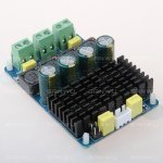
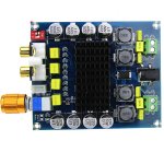
I compared Mono TDA7498MV to TPA3116D2 & I found the former (TDA7498MV) to be better in clarity albeit slightly higher noise.
Tested with 19v HP laptop adapter & Dayton RS100 with bullet tweeters.
Left red board TDA7498MV - Right blue board mono TPA3116D2
Tested with 19v HP laptop adapter & Dayton RS100 with bullet tweeters.
Left red board TDA7498MV - Right blue board mono TPA3116D2
Attachments
Last edited:
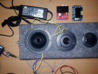
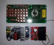
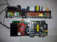
Hence decided to make a monoblock with TDA7498MV with SMPS, DC Filter circuit & 6db crossover.
First picture is the motherboard to which the TDA7298MV & SMPS pre-made boards are mounted. Second is the finished monoblock with plastic spacers (to prevent any shorts).
Tried with both 12v & 24v SMPS. Found 24v to be better in vocal \ treble clarity.
Also better at high volumes at reducing speaker 'pop' \ distortion sound. Speakers used were Dayton ND91-4 & ND20FB-4
Attachments
Last edited:
I finally got this unit from sanwulasers and after figuring out I ordered the wrong one (I was wanting the version with more film caps for an extra buck) and some preliminary testing I can say with a great deal of confidence that these counterfeit Sanyo WG deserve a new home in the trash bin. After leaving on overnight, the caps are already bulging. Sound out of the unit is ok, not particularly special, but I'll reserve judgement until the replacement caps come in. Must say the heat sink gets pretty hot to the touch, about 60 C.
Just curious, when you leaving it on overnight, did you have a load on the output? Were you playing music? Can you tell us what kind of preliminary tests you had done on the amp?
Regards,
The unit was connected to 8 ohm speakers and had music running at low volume. Power supply was a 32V 3A brick. These fake Sanyo WGs have been around a long time (I see someone complaining about them in 2006). The vent is wrong for Sanyo and the 1000uf/35V value does not exist on the datasheets. I have some ZLH and FC caps on the way for replacement. I will measure the voltage at the caps before changing them. The output filter is set up for 8 ohm speakers and I'm planning to adjust per the datasheet for 6 ohm. And I will post a picture of the underside of the heat sink, I think I may have checked some of the values there and they appeared to be in line with the datasheet, but all of these little Class D amps are running together on me.
Out of the box, this unit does not sound as good as my reference Class D amp, the first generation modified Sure TA2024 we were all talking about back in 2007. It remains easily the best sounding Class D amp I have used and I found a possible supplier of the original board on Taobao, but am unable to figure out how to order it.
sureelectronics Tripath boards?
I'm wondering if anyone else has tried the XH-M512 version of this board? It seems well made 50V caps etc but the biggest potential advantage is there are several sellers with it fulfilled by amazon so I was able to get it in a couple days vs a couple weeks from the Chinese sites.
I'm running it on a 90W laptop brick connected to 6 ohm speakers and it sounds pretty good.
That said I'm not sure if it's operating correctly and was wondering if anyone else has a TDA board that does too:
If the board is unplugged and in standby after powering it up the speakers are silent. Once the board is taken out of standby there's a bit of noise (soft hiss) from the speakers. Even after putting it back into standby the noise remains until unplugged again.
I'm wondering if anyone else's standby behaves like this? Shorting the mute pins does nothing to the hiss but will mute if playing audio.
Attachments
After leaving on overnight, the caps are already bulging. Sound out of the unit is ok, not particularly special, but I'll reserve judgement until the replacement caps come in. Must say the heat sink gets pretty hot to the touch, about 60 C.
I have the same amp. Did u change the caps?, if significantly improved which caps do u recommend?
- Status
- Not open for further replies.
- Home
- Amplifiers
- Class D
- Ebay cheap TDA7498 boards