Hi Oli,
The 40KHz fc point is realised with a 5x bigger roll-off cap..
I'm sorry to dissapoint you but 3Vpp is not going to happen for this circuit.
The problem is that -5/+5 volt supplies don't give much room for CCSes and thus the upper bias resistor also determines the voltages out.
I think -0.6/+0.6V is what you get with this one (-2mA / +2mA in).. you can streatch it abit.. but you might want to try a discrete opamp instead for higher output...
Regards,
Thijs
PS
I think a CCS like Jocko's circuit would need atleast .. ehhhhh .. 0.6V (Vbe) + 0.6 (for I bias) + 1(?) volt for Vcb .. that's 2.2V for the upper CCS ....from the 5V you are leaved with 3.8V... take again 0.6 + 1V =1.6V for the middle thansistor.. you are leaved with 1.2 V .. hmmmmm that's not that bad .. Did I just make a mistake?
let's see what Spice has to say about that...
I'll get back to you ...
OK .. so I made a mistake .. actually at least two .. please don't kill me .. 5V minus 2.2V is 2.8V not 3.8V .. this would be the upper maximum output voltage .. 0V plus 1.6V is 1.6V and this would be the minimum output voltage .. that leaves 2.2Vpp for output swing.. right? hmmmm not bad .. Jocko's circout should work at -5 / +5 V allthough precise biasing would be an issue bias you could use 560 Ohm for a -2mA/ +2mA output DAC...
Jocko .... where are you.. stop about your mail ...
Regards,
Thijs
OK, just in time for an edit...
It's late, ... too much beer .. can't .... get /// the ... numbers ... wwwwwwright ...
...
swing is 2.8 minus 1.6 = 1.2 Volt .... still OK to me.... I have said it many times; I don't use more than 4Vpp at my speakers .. check yours ... see what kind of voltage swing you need...
Jocko .... where are you.. stop
about your mail ...Regards,
Thijs
OK, just in time for an edit...
It's late, ... too much beer .. can't .... get /// the ... numbers ... wwwwwwright
... swing is 2.8 minus 1.6 = 1.2 Volt .... still OK to me.... I have said it many times; I don't use more than 4Vpp at my speakers .. check yours ... see what kind of voltage swing you need...
I have two questions for jocko and/or others:
Will this circuit work on +/- 14V?
Why don´t you try Jocko´s I-V stage ?
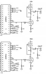
I am a nearly an newbee on this,but I wonder if it will work with +/- 12v (jocko´s I/O conv.) and I´m planing to have a tubeoutputsage,can R1 be as low as 2,49 ohm,what about say 10K?And some one mentions a filter at 200Khz or 40Khz,on the picture I´ve added I can´t see any filter.will it work without a filter,or better with a filter?
As I said newbee.
Thanks Nicke for the link!
Attachments
>if it will work with +/- 12v
Yes, it will work. Current sources with LEDs needs about 2V across to operate.
>will it work without a filter,
It will work without filter. As Jocko said, you can add jfet follower.
>Why don´t you try Jocko´s I-V stage ?
Try it, you won't be sorry.
Have a nice day
Yes, it will work. Current sources with LEDs needs about 2V across to operate.
>will it work without a filter,
It will work without filter. As Jocko said, you can add jfet follower.
>Why don´t you try Jocko´s I-V stage ?
Try it, you won't be sorry.
Have a nice day
Hi,
What's R1 on your schematic? The resistor in series with the grid, close to the #7 on your drawing?
If so keep it small, anything from say 33R to 1K will work fine provided you put the resistor as close as possible to the grid of the tube.
The resistor right in front of it and that is in shunt with the input is serving as the I/V resistor and doubling as gridleak resistor.
The circuit works fine without filternetwork. Whether it sounds better either way I leave to the Audiogods in the sky to decide.
BTW, if anyone can point me to Jocko's I/V circuit so I can take a look at it?
After that I may be able to help you all better.
Cheers,")
can R1 be as low as 2,49 ohm,what about say 10K?And some one mentions a filter at 200Khz or 40Khz,on the picture I´ve added I can´t see any filter.will it work without a filter,or better with a filter?
What's R1 on your schematic? The resistor in series with the grid, close to the #7 on your drawing?
If so keep it small, anything from say 33R to 1K will work fine provided you put the resistor as close as possible to the grid of the tube.
The resistor right in front of it and that is in shunt with the input is serving as the I/V resistor and doubling as gridleak resistor.
The circuit works fine without filternetwork. Whether it sounds better either way I leave to the Audiogods in the sky to decide.
BTW, if anyone can point me to Jocko's I/V circuit so I can take a look at it?
After that I may be able to help you all better.
Cheers,
Hi,
Ah...It's still that old thread Jocko started over a year ago...
My bad for not looking in the obvious places.
Thanks anyway.
As far as I can tell, why not?
Ryssen,
The circuit you posted does I/V already (from the little I can actually decypher on it) , so if you stick with the SRPP stage, using a ECC88/6DJ8 for the tube, you'll also have sufficient gain and low enough Zo to drive a 20K Zin or higher.
Provided you keep cable length short and low in parasitic capacitance and you're willing to fit the extra PS for the tube's B+ and heater it should work great.
Cheers,
The schemtatic of the circuit I'm reffering to is in first post of this thread. It is posted by Jocko Homo....
Ah...It's still that old thread Jocko started over a year ago...
My bad for not looking in the obvious places.
Thanks anyway.
Could anyone tell me if I could use Jocko's I/V for the TDA1543 based dac? I am not sure......
As far as I can tell, why not?
Ryssen,
The circuit you posted does I/V already (from the little I can actually decypher on it) , so if you stick with the SRPP stage, using a ECC88/6DJ8 for the tube, you'll also have sufficient gain and low enough Zo to drive a 20K Zin or higher.
Provided you keep cable length short and low in parasitic capacitance and you're willing to fit the extra PS for the tube's B+ and heater it should work great.
Cheers,

any more info regarding....
Hi all,
Im about to build this I/V converter, but Im not sure what I need to do to install it into my Phillips cd650, I have read for hours trying to find more info regarding installing these but cant find anything regarding these questions.
1/. I know where my i2s out is on the dac, and that it goes into the I/V convertor, but im not sure if I have to remove anything in the path or is it straight from chip output to i/V input?
2/ Should I use 18V or 24V for the power supply, at this stage either is easy to build.
3/ Is LM431 ok for regulation?
4/ For now I wont add a follower, cos I dont have any jfets or a simple non jfet design. Is it ok to feed this straight to rca output and if so will I get turn on thumps?
Can I feed its output back into the op amp buffer stage?
thanks Arthur
Re: any more info regarding....
1) no you dont. i2s is input for the dac (coming from 7220). the dacs current outputs should go into the i/v convertor. You will have to remove the current connection to the i/v opamps.
have a look at the 1541 datasheet and good luck.
Luke said:Hi all,
1/. I know where my i2s out is on the dac, and that it goes into the I/V convertor, but im not sure if I have to remove anything in the path or is it straight from chip output to i/V input?
2/ Should I use 18V or 24V for the power supply, at this stage either is easy to build.
3/ Is LM431 ok for regulation?
4/ For now I wont add a follower, cos I dont have any jfets or a simple non jfet design. Is it ok to feed this straight to rca output and if so will I get turn on thumps?
Can I feed its output back into the op amp buffer stage?
thanks Arthur
1) no you dont. i2s is input for the dac (coming from 7220). the dacs current outputs should go into the i/v convertor. You will have to remove the current connection to the i/v opamps.
have a look at the 1541 datasheet and good luck.
hi Guido,
thanks for the reply. I just upgraded my clock to one of your Xo clocks. I must say I was very sceptical but felt complelled to try it anyway. Its probably the best upgrade for the money you can make to a cd player. Thanks.
I got my terminology wrong, but I know what the outputs are from TDA1541. They will feed Jockos I/V convertor.
In the cd player there are two opamps per channel are there not? One is i/v converter one is output buffer. Between them is a couple of resistors and caps. Should I take output from Jockos I/V straight to RCA out?
cheers ab

Luke said:hi Guido,
They will feed Jockos I/V convertor. In the cd player there are two opamps per channel are there not? One is i/v converter one is output buffer. Between them is a couple of resistors and caps. Should I take output from Jockos I/V straight to RCA out?
cheers ab
happend before. As for the above, it seems about right.Mind you to shorten the old i/v input to ground, otherwise the opamp will bring down the powersupply

Dont know Jocko's I/V, so this is for somebody else to answer.
GuidoB (!= GuidoT)
Purpose of I/V Converter
I'm new to the DIY DAC project threads. Can someone explain just what the Current to Voltage converter is used for....why is it necessary....or is it? Do all DACs need this to output to an amp? Do some DAC kits have it already built in as part of the main pcb?
I'm new to the DIY DAC project threads. Can someone explain just what the Current to Voltage converter is used for....why is it necessary....or is it? Do all DACs need this to output to an amp? Do some DAC kits have it already built in as part of the main pcb?
OK, I'll bite.
The need for an I/V converter is not universal, but is essentially intrinsic to the operation of the majority of DAC realisations used for audio.
Construction of a DAC capable of the resolution needed for audio is not trivial, 16 bits equals 65536 discrete levels. 24 bits, 16.7 million. Useful DAC topologies that are suitable for lower resolutions (which at an extrema include the segmented DAC with a switch and internal level generator for every possible output level) are simply impossible. One of the most popular topologies for audio is the R2R. With a very clever layout a set of switches (one per bit) and only a small number of resistors (2 per bit) with only two values, one twice the other (hence the name), an accurate and realisable DAC is possible. The resistor network is fed from a stable voltage source, and thus is essentially a source of current. Interestingly it is not correct to terminate it into another resistor and call it a potential divider, the mathematics of the R2R network only works when fed into zero impedance. (But the error seems benign, and there are many adherents to using a suitable low value resistor.)
Another important reason for DACs running in current mode is that many very high clock rate converters - typically the delta-sigma converters - require significant reconstruction filtering, and this can be performed with switched capacitor filters - which are a current mode topology.
So, what we need is a zero impedance device that converts current into voltage. Clearly if the requirement were not zero impedance, a resistor would be perfect, as Mr Ohm tells us. The conventional manner of performing I/V conversion is a trans-impedance amplifier. Where the virtual ground of an op-amp provides the zero impedance point. The general dislike of trans-impedance amplifiers stems in part from the difficulty in creating a real op-amp that is capable of operating at the very high slew rates that are intrinsic with a discrete sampled signal. Indeed at the frequencies involved it is not clear that the trans-impedance amplifier is operating as anything like a textbook op-amp. So we have many other clever circuits that provide I/V conversion.
So, many DAC ICs are current output devices - albeit ones with a far from ideal nature, with quite noticeable output impedance. It is then left to the designer of the system to implement a conversion to the voltage levels needed elsewhere - along with providing whatever final filtering is needed. There are quite a number of DAC chips that are voltage output - however these are almost invariably simply the sibling of a current output DAC with an additional internal trans-impedance amplifier. With the consequent quality issues.
I/V Purpose
Thanks Francis Vaughan.....that is very helpful. I'm a structural engineer by trade, and as such my understanding of electronics is somewhat rudimentary. 'Big picture' concepts are helpful.
I ordered a DAC-1 kit from Rockna, but it has not arrived yet. I noticed they also have an I/V converter kit and I am not sure if I need that or not. I suspect their DAC outputs in voltage mode, but I don't know yet, and communication with them has been difficult.
- Status
- This old topic is closed. If you want to reopen this topic, contact a moderator using the "Report Post" button.
- Home
- Source & Line
- Digital Source
- Easy-to-build I/V stage