Re: Is discrete transistor I/V conversion an option at +/-5(five) Volts
Hi Oli,
Just fill in the values for a first order filter in FilterPro.
Your choice: the crossoverfrequecy.
With a unity gain stable opamp it should work.
Just the first part of my scheme.
My best guess at Jocko's circuit you will find here:
http://www.diyaudio.com/forums/showthread.php?postid=201512#post201512
Oli said:Hi everyone!
(Hi Elso - This thread seemed more appropriate for a discussion of my I/V conversion)
I have been recently looking at op-amp I/V conversion for my single ended output AD1865N-K project. I am currently using the internal opamps and attempting to shunt HF to ground in the form of a first order filter (To cut a long story short.. I am loading the input of the opamp with capacitance- making it unstable!)
I am looking at my options... I only wish to use +/- 5 (five) Volt supplies.
Can Jocko's zero feeback discrete I/V converter be adapted - I would love to give it a try?
How can I first order filter with an opamp for my AD1865N-K.
Your thoughts please...
Hi Oli,
Just fill in the values for a first order filter in FilterPro.
Your choice: the crossoverfrequecy.
With a unity gain stable opamp it should work.
Just the first part of my scheme.
My best guess at Jocko's circuit you will find here:
http://www.diyaudio.com/forums/showthread.php?postid=201512#post201512
Hi,
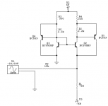
I think this could be a discrete easy-low-voltage IV-stage. The CFP does a great job lowering the input impedance and lowering the distortion. Needs to adjust the input Vdc .... it's just a circuit I had for a while now.... finaly a reason to post it..
What do you think Elso?
IS Jocko still around? It challences your circuit for low input R I think, but that might not be sooooo important........
Regards,
Thijs
Attachments
A final question- about filtering....
Thanks.. So if I just connect to the junction at R2-R4 and a.c. couple this with a suitable non polar capacitor I am in business?
A final question, then I must go...
I am using a non-oversampling setup and I wish to use a first order filter (at say 200kHz) to remove excess r.f. garbage from the signal chain and affecting my power amplifiers. Will your circuit accept a simple RC filter at the output or should it go elsewhere?
jean-paul said:X-pro, is that a MF schematic ?
No. This circuit was never in production AFAIK. (And I would never publish somebody else's circuit anyway - this one is my own design from 1994).
x-pro
Re: Filter Pro does not allow it!
Hi Oli,
I am sorry never tried a first order filter with FilterPro. I did not work indeed.
Yes I guess your formula is right. I calculated 270pF with a 3k feedback resistor.
Oli said:Elso,
Using filterpro I cannot build the first section in isolation
Have a go and you will find it will not work!
Is this simply a case of f=1/(2*pi*R*C)
Hi Oli,
I am sorry never tried a first order filter with FilterPro. I did not work indeed.
Yes I guess your formula is right. I calculated 270pF with a 3k feedback resistor.
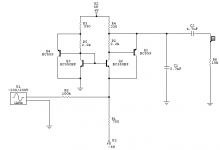
I've just posted a versions with output cap and HF roll-off cap. This would give you the disered -3dB at 200KHz (or about).
Do you really think your amplifier responds to 200KHz? If so, -9dB at 400KHz is not a large attenuation ... I think you could easely put a fc at 40KHz.
Regards,
Thijs
Do you really think your amplifier responds to 200KHz? If so, -9dB at 400KHz is not a large attenuation ... I think you could easely put a fc at 40KHz.
Regards,
Thijs
Attachments
X-PRO,
Is there a specific reason to connect R12 to the base of Q2 ?
Couldn't R12&R6 be just one resistor between the current source and sink ?
You seem to use a LED constant current source, as well as 2-transistor constant current sources. Any reason why you didn't use LED ccs throughout ?
Is there a specific reason to connect R12 to the base of Q2 ?
Couldn't R12&R6 be just one resistor between the current source and sink ?
You seem to use a LED constant current source, as well as 2-transistor constant current sources. Any reason why you didn't use LED ccs throughout ?
tbla said:is this the output stage from the exposure cdplayer...?
As I've posted earlier, this design never went into production. And I never worked for Exposure
. x-pro
Thanks Tschrama- perhaps 40kHz is better
Tschrama,
Thanks for the modified cicuit. Perhaps my 200kHz choice is a little inappropriate- How could I modify component values for a more sensible 40kHz cutoff?
I desire a suitable voltge output from this circuit (e.g. 3V peek to peek). Do I have to adjust any resistor values to get this from the current output of the AD1865?
- Status
- This old topic is closed. If you want to reopen this topic, contact a moderator using the "Report Post" button.
- Home
- Source & Line
- Digital Source
- Easy-to-build I/V stage