As in post #1 here using a 2N7000 FET. A small NPN transistor is OK too. Kake sure it is in contact with the main heatsink.
http://www.diyaudio.com/forums/soli...-hexfet-poweramp-sonic-benefits-approach.html
http://www.diyaudio.com/forums/soli...-hexfet-poweramp-sonic-benefits-approach.html
Hi shravanth,
The schematic you posted in Post #94 is here :
25 Watt MosFet Audio Amplifier - RED - Page2
If you want to get more power by using IRFP240, 9240, you might want to take a look here :
60 Watt MosFet Audio Amplifier - RED - Page100
Wonder if you have gone thru all of this thread. I had mentioned earlier that I had tried both of these with the original design and both are working. It doesn't need laterals to work. The original designer has specifically told me that these design need no Vbe or they would be over compensation. Don't know why you guys just don't want to believe in what others had designed and made. I had used it for more than 6 months w/o a glitch.
There is the wall and the door to the project. If you want to go thru the door, great. If you want to bang the wall, it is your own fun, enjoy it.
BP
I use irf530/9530. Others as specified. I did not use it for too long because I fell in love with another one, the AV400 by Holton. BTW, the 25w was my first ever project on power amp. I then redo with a pcb that have 2 channels on it and 1 channel is the mirror image of the other. Pretty tricky. If the circuit has been more complicated, it may not had been done. In fact that was the only one I had done as 'butterfly'. Should have done the same on the 90w but the board was laid in a hurry. the 25w has a footprint size of 75mmx145mm while the 90w is slightly bigger. I still have a few pieces with me and if you are interested call me
tony_chan_cf@email.com
BTW, I also have boards for AV400.
It's a simple project, might as well see for yourself the performance. I would say : you won't be disappointed .
tony_chan_cf@email.com
BTW, I also have boards for AV400.
It's a simple project, might as well see for yourself the performance. I would say : you won't be disappointed .
Did you implement the bias circuit with a transistor with a resistor between C and B and between B and E ? This circuit mount to the main heatsink and connect between the bases of the driver transistors.
Without this circuit, the amp will go into thermal runaway unless its biased into class B or using lateral mosfets.
All IRF and IRFP type mosfets are vertical mosfets = the Vbe multiplier circuit stated above is mandatory in order for the amp to be biased into class AB.
To get an idea on what i am talking about: http://i.imgur.com/pued8.png <-- the BD139 with the resistors and the cap.
Here it can be seen on the main heatsink: http://i.imgur.com/KqTRW.jpg
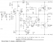
Now back to basics...a design that is "easy and low cost". May I suggest the Citation 12 MOSFET with my take on updated parts. Could use an input cap. Use good electrolytic caps like Silmic II's. The man himself said it has a "detailed and sweet sound".
Attachments
Pelatuk amplifier with OITPC compensation:
https://www.diyaudio.com/forums/solid-state/338815-anistardi-peletuk-4.html#post5835050
PCB layout:
https://www.diyaudio.com/forums/solid-state/317335-oitpc-output-inclusive-tpc-tmc-11.html#post5609013
https://www.diyaudio.com/forums/solid-state/338815-anistardi-peletuk-4.html#post5835050
PCB layout:
https://www.diyaudio.com/forums/solid-state/317335-oitpc-output-inclusive-tpc-tmc-11.html#post5609013
- Status
- This old topic is closed. If you want to reopen this topic, contact a moderator using the "Report Post" button.
- Home
- Amplifiers
- Solid State
- Easy and low cost: IRF540/9540 amp