Hello,
For both stages I used a red led on cathode.
They are the input led of some optocouplers I had in my junk box.
They had the voltage drop I needed to get the right anode current.
Maybe tomorrow I can post some pictures.
BR
Luca
Hi Luca,
Thank you very much.
BTW, according to Thorsten, diodes, including LEDs, are less linear than any electrolytic capacitor.
I have some E810f's.
Why would there be a problem to use a voltage regulator? With a Phono pre-amp.
I would use a tube regulator.
Phil
Hi Phil,
There is no problem with using the right voltage regulators in phono stages.
There is a problem with VR tubes, since they are noisy.
BTW, according to Thorsten, diodes, including LEDs, are less linear than any electrolytic capacitor.
Context and analysis are a better approach than pronouncements.
Keep the voltage swings required in mind when thinking about linearity in general.
Remember that your PSR for a pentode input is effectively nonexistent.
Good luck.
Context and analysis are a better approach than pronouncements.
Keep the voltage swings required in mind when thinking about linearity in general.
Please argue with Thorsten, I only quoted him.
Good luck.
Thank you.
Please argue with Thorsten, I only quoted him.
He may or may not be correct, depending on the situation and the context. Your reduction to a rule is clearly incorrect.
Hello,
using a LED to bias doesn´t solve the stability problems. I´ve tried it. You still will have problems to find matching pairs. The operating point is solid as a rock with the positive g1 voltage and the high value cathode resistor.
I first was a bit afraid about the additional coupling capacitor which is needed between MC step up and g1. Surprisingly, it sounds better with it.
Regarding the VR tube, I only changed one channel to a 0A2. I couldn´t hear any differance regarding noise. But it sounds clearer. Less distortion.
Best regards,
Martin
Hello Martin,
I wasn't aware of any matching problem.
With the original back bias I wasn't able to have stable currents.
With LEDs the anode currents of E810F and D3A were decently similar for the L and R channels.
No other check since then (2009).
I will do soon...
Best regards
Luca
I wasn't aware of any matching problem.
With the original back bias I wasn't able to have stable currents.
With LEDs the anode currents of E810F and D3A were decently similar for the L and R channels.
No other check since then (2009).
I will do soon...
Best regards
Luca
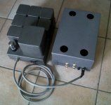
Hello,
Here is the pic, sorry for the low quality image.
The (heavy) box on the left is the PS.
As per Thorsten project it is unregulated.
I only made it with 3 LCL stages instead of 4.
Happy New Year to All.
Luca
Hi Luca,
It looks nice.
Is the phono stage completely quiet, free of any hum?
Happy New Year.
Hello,
using a LED to bias doesn´t solve the stability problems. I´ve tried it. You still will have problems to find matching pairs. The operating point is solid as a rock with the positive g1 voltage and the high value cathode resistor.
I first was a bit afraid about the additional coupling capacitor which is needed between MC step up and g1. Surprisingly, it sounds better with it.
Regarding the VR tube, I only changed one channel to a 0A2. I couldn´t hear any differance regarding noise. But it sounds clearer. Less distortion.
Best regards,
Martin
Hi Martin,
What is stability issue you encountered with the original design? Was it difference in anode currents between the 2 channels, or what?
What capacitor did you put before g1 of the first tube?
Can you describe the sound difference when you added that capacitor?
That regulating the voltage supplied to g2 decreases distortion does make sense. However a maida-like regulator can do the job well. It looks to me better to avoid any noise-producing elements inside a phono stage.
Happy New Year.
Hello,
I have all the irons (transformers, chokes for PSU and EQ) custom made in Italy.
Because sometimes I collaborated with the manufacturer I don't know if it is correct to disclose here who is.
The unit itself is quiet enough (no noticeable hiss) and with little hum.
But since then I have to deal with external MC pre-pre.
Until now I can't make it quiet enough because both SUT and single FET (similar to that proposed here by Salas ) are quite humming.
Best regards
Luca
I have all the irons (transformers, chokes for PSU and EQ) custom made in Italy.
Because sometimes I collaborated with the manufacturer I don't know if it is correct to disclose here who is.
The unit itself is quiet enough (no noticeable hiss) and with little hum.
But since then I have to deal with external MC pre-pre.
Until now I can't make it quiet enough because both SUT and single FET (similar to that proposed here by Salas
) are quite humming.Best regards
Luca
Hello,
Different anode currents resulting in quite different voltages. Also the gain was quite different. Now I can plug almost any E810F resulting in a very stable operation point. AC as well as DC. Give or take 1V.
220nF with a 910K grid leak resistor. In theory a 10nF would be enough but it sounded better with a larger cap. By the way, by using the postive g1 voltage you can increase the grid leak resistor up to 3M5.
I always have problems to explain how things sound. I guess you´ll have to find it out by yourself. I like it
Distortion reduction only worked by connecting the 0A2 to the cathode. There was no change in distortion if connected to ground. There was also some noise.
Happy New Year!
Best regards,
Martin
What is stability issue you encountered with the original design? Was it difference in anode currents between the 2 channels, or what?.
Different anode currents resulting in quite different voltages. Also the gain was quite different. Now I can plug almost any E810F resulting in a very stable operation point. AC as well as DC. Give or take 1V.
What capacitor did you put before g1 of the first tube?
220nF with a 910K grid leak resistor. In theory a 10nF would be enough but it sounded better with a larger cap. By the way, by using the postive g1 voltage you can increase the grid leak resistor up to 3M5.
Can you describe the sound difference when you added that capacitor?
I always have problems to explain how things sound. I guess you´ll have to find it out by yourself. I like it
That regulating the voltage supplied to g2 decreases distortion does make sense. However a maida-like regulator can do the job well. It looks to me better to avoid any noise-producing elements inside a phono stage.
Distortion reduction only worked by connecting the 0A2 to the cathode. There was no change in distortion if connected to ground. There was also some noise.
Happy New Year!
Best regards,
Martin
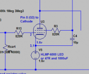
Hi Jushua,
If you go for the LED bias option, use an HLMP 6000 series LED for the bias; these have really nice curves.
The E810F will oscillate in the box, carbon comp stoppers on the grids and ferrites on all pins; the one I'm building now has 2k2 grid stoppers.
Don't worry about the pentode partition noise, E810F is designed for instrumentation use, very very quiet!
As Martin said AC reference g2 to the cathode, I used a 10uF cap, bit like the attached.
Attachments
Hi Andrew,
Thank you.
I intend to start with Thorsten deign as it is. Once it will be running and (hopefully) singing, I may try some modifications.
Carbon composite grids stoppers and ferrite beads are obvious, as well as mounting the tubes sockets on some rubber O-rings. (Rubber in a manner of speaking, since plain rubber rings will lose their elasticity under heat).
One thing I may try is about 0.3V bias (not much higher), to maintain as much transconductance as possible and provide some stability. I also may try positive voltage to g1 (with the obvious needed adjustment to the cathode bias). However, should I do that I'll go for bypassed resistor, not nay diode or LED.
I may also try maida-like regulator to g2.
In any case, referencing g2 to the cathode is an excellent idea, in the way of ultra-path.
- Status
- This old topic is closed. If you want to reopen this topic, contact a moderator using the "Report Post" button.
- Home
- Amplifiers
- Tubes / Valves
- E810F and general pentodes design question