The filter is a 2nd order Butterworth, Fc=288.6kHz.
So I've been looking around to try and learn about filters...
Didn't learn much, but it seems that the topology used in the 0404 and also suggested in the AKM datasheet is a "Multiple Feedback Filter".
A good description is for example here, where they also show the differential version, that interests us.
Our values would give a cutoff frequency of 206 KHz.
It seems like the Bessel/Butterworth/etc "response shape" applies somehow to MFB filters as well... is it in the relative values of R-s and C-s ?
In fact other V-out DACs, like Wolfson and NPC, show the more usual Sallen-Key filters. They too, come with or without the coupling capacitors...
This doesn't change much to our previous findings, just wanted to document it.
The wiki is still blocked on a pending moderation...
I try to attract the attention on this, but everybody seems busy elsewhere...
-
Last edited:
Hello everybody. I just updated and fixed some stuff in the wiki.
Mainly:
Best
Mainly:
- 470uF and even 220uF filtering caps will potentially make the board unstable. I'm trying to get some feedback out of 100uF.
- Found the purpose of OWNK N-JFET trannies. They mute outputs at immediate turn on, so that speakers won't bump.
- Added some infos about changing opamp rail supplies
- Added some thoughts about be-or-not-to-be of DAC decoupling caps
- Fixed image size, links, post DAC schematic and other minor stuff
Best
I'm having a strange problem. After some modifications related to the post DAC, the inputs don't work correctly anymore. They sound like impedance mismatch is happening, plus a lot of hiss is present. I haven't ever played around input sections so I'm just wondering how the hell went wrong. Any ideas? :\
Op Amp comparison
Been off of this thread for a while, but I got to a point where the next thing to do is to test "external" output stages, not just to tweak the card. And I am not very fast at building things...
To start, I wanted to compare different op amps used as "summing filters" like in the basic schematic (but without coupling caps out of the AKM4396). So I built two identical circuits with sockets, each with its own "local" regulators (78/7912) and some decoupling. These can be A-B switched: I have these ITT telecom relays with a 6-poles, and that's quite convenient for in+, in-, out, on 2 channels.
In terms of op amps (duals only... too complicated otherwise) what I had at hand are LM833, C4570, JRC4560, OPA2604, OPA2134 and a thing marked OP271.
To make the test blind, I had an "assistant" (my 10-year old son...) put a piece of tape over the chips, and mark them A to E (the OP271 was excluded, since the package makes it too easy to recognize - it didn't sound right anyhow, in a non-blind comparison...)
Then I ran "each against each".
The results are somewhat different from what I expected...:
Ok, the winner is OPA2134, that consistently beats all others.
But then, second place is C4570. Unexpected to me...
Honorable third is 4560, whose full bass deserves to be mentioned.
Then LM833.
Disappointing was the OPA2604, that sounded harsh and narrow.
(But this chip hadn't been used much, maybe it has to burn in?)
Each step of this ranking is a noticeable difference on the one below, in terms of "width" of the soundstage and precision of the instruments, like nicer decays, or more silky (realistic) string instruments.
So for this experiment, despite non-optimal conditions (sockets, relay, long connectors from the DAC) I can report that replacing op amps does make a difference. And OPA2134 is indeed good value.
Just thought I would report.
Next: extract the 2608 and 5532 from the e-mu and A-B compare these with some of the others. But they're smd, so it may take another while...
_
Last edited:
Yes, I am aware of that.
No general conclusions can be drawn from this cheap experiment, which has a limited scope.
The circuits I compared are at the quality level that I can implement myself, which I know is not extremely high.
Nevertheless:
- The op amps I compared are not really very fancy, so the risk of misbehaving seemed low.
Only the OPA2604 datasheet describes specific optimization;
indeed I cannot exclude that it is the reason of its disappointing behaviour.
- I did apply some basic measures, like regulators very close to the op amp (< 1 cm), caps from supplies to ground and a cap across the supplies.
- I paid attention to signs of instability, like overheating or noises; didn't detect any.
So my conclusion should be
"I should not use in this cheap circuit the op amps that deserve better optimization".
That's still valid, isn't it?
But it's clearly not the opamps' fault.
I chose to not go for very high performance components, since I wouldn't really know how to use them at their best.
Maybe I will try to build a better circuit, especially for the OPA2604.
And then compare it with the gross one.
By the way, this whole playing around we're doing on the eMu 0404 is really not "unconditional highest end".
We're on the cheap side of things.
I still think some small improvements can be reached with a relatively small effort.
You are right that we should be lucid about these limitations.
_
EMU 0404 Headphone mod gone wrong
I replaced the opamp and two caps in the headphone section and now I have very low output. Both channels work but they can be driven into distortion very quickly.
I changed the opamp out trying a couple of different opamps just to see if I had a bad opamp but it yields no difference. Any ideas what I may have done???
Thanks
JJHaz
I replaced the opamp and two caps in the headphone section ...
Which caps did you change, what is their marking on the PCB?
Sorry if it's obvious, but some first things to check would be orientation of the op-amp (pin 1 on the correct side) and polarity of the caps, if electrolytics.
Also check that the supply pins (4 and 8) of the opamp get the correct voltage, should be around -6V and +6V respectively.
-
hi I also have a question regarding pot: whats its sizes and especially shaft length? I'm planning to do some upgrade of my EMU, including pot replacement (old one weared a bit). But before ordering new pot I need know sizes of old one, and if somebody knows that - I will not do unnecessary disassembling just to make measurements..
BTW I'd like to select something from this list - may be somebody already did this and can point matching replacement?
BTW I'd like to select something from this list - may be somebody already did this and can point matching replacement?
Last edited:
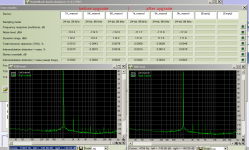
Just completed part of upgrade. Aim was to improve EMU not only as DAC for sound listening but also as measurement tool - so for post-DAC stage and left channel pre-ADC stage I replaced NJM2068-s with LM49860-s, NE5532-s - with OPA1612-s. Also I did pre-ADC left channel wire workaround to reduce inductor's interfering.
Testing results (with THD measured at 1KHz, 5KHz and 9KHz) attached. Note that noise level become a half-of-db worse (from eye-weighted look I'd say that noise level actually become lower but let assume RMAA gave correct numbers..), but this happened after pre-ADC modification, when only post-DAC opamps were replaced noise level was same as before modification. However pre-ADC modification improved a bit THD results and I decided to left it as is. Also on graph you can see that bunch of high-frequency spikes disappeared after upgrade. This is due to left-channel wire-around fix.
Testing results (with THD measured at 1KHz, 5KHz and 9KHz) attached. Note that noise level become a half-of-db worse (from eye-weighted look I'd say that noise level actually become lower but let assume RMAA gave correct numbers..), but this happened after pre-ADC modification, when only post-DAC opamps were replaced noise level was same as before modification. However pre-ADC modification improved a bit THD results and I decided to left it as is. Also on graph you can see that bunch of high-frequency spikes disappeared after upgrade. This is due to left-channel wire-around fix.
Attachments
Last edited:
Just completed part of upgrade. Aim was to improve EMU not only as DAC for sound listening but also as measurement tool - so for post-DAC stage and left channel pre-ADC stage I replaced NJM2068-s with LM49860-s, NE5532-s - with OPA1612-s. Also I did pre-ADC left channel wire workaround to reduce inductor's interfering.
Testing results (with THD measured at 1KHz, 5KHz and 9KHz) attached. Note that noise level become a half-of-db worse (from eye-weighted look I'd say that noise level actually become lower but let assume RMAA gave correct numbers..), but this happened after pre-ADC modification, when only post-DAC opamps were replaced noise level was same as before modification. However pre-ADC modification improved a bit THD results and I decided to left it as is. Also on graph you can see that bunch of high-frequency spikes disappeared after upgrade. This is due to left-channel wire-around fix.
misterzu, very usefull information.
There is a same approaching at the posts 112, 117, 133, 167, 168 at the thread USB vs PCIe Sound Card for audio analysis.
You used the RightMark Audio Analyser Pro. Sure is the good software but is much robotic to their results.
Please, if you have the time repeat the thd measures with ARTA & STEP(part of ARTA) softwares.
I am very interesting if the thd improvement that you haved will repeat and with the ARTA software.
That mean I need to desolder new opamps and put old ones instead just to measure and then exchange them again... Nope
BTW looking at pics on your link I see (not first time) that people tend to replace all opamps, including U16. Why? According to schematic on wiki and my quick checks its only pre-headphone buffer and doesn't affect lineouts. I didn't replace it since I don't use on-board headphone amp.
BTW looking at pics on your link I see (not first time) that people tend to replace all opamps, including U16. Why? According to schematic on wiki and my quick checks its only pre-headphone buffer and doesn't affect lineouts. I didn't replace it since I don't use on-board headphone amp.
Last edited:
You don't need to desolder the opamps. There is a lot of information about factory measurement.
If you have the time, repeat your RightMark Tests (as it now your emu) with Arta & Steps.
Yes you have right, people tend to change all the opamps at the DAC stage.
You didn't replace the U16. Did you left and another opamps to ADC stage or change all of them?
If you have the time, repeat your RightMark Tests (as it now your emu) with Arta & Steps.
Yes you have right, people tend to change all the opamps at the DAC stage.
You didn't replace the U16. Did you left and another opamps to ADC stage or change all of them?
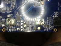
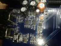
On attached photos:
postDAC: U22 -> LME49860, U33, U39 - OPA1612
preADC: U1 -> OPA1612, U9, U12, U15 - LME49860
I didn't replace pre-ADC stage of right channel cuz usually use only left channel for measurements, also U2 opamp is places very inconveniently to desolder.
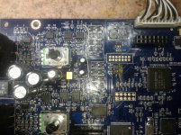
Also I'm interested whats U3/U7 on unknown.jpg. I assumed they're related to direct monitor functionality, but not sure...
All measurements I did using unbalanced in/outs. IMHO this is more informative.
postDAC: U22 -> LME49860, U33, U39 - OPA1612
preADC: U1 -> OPA1612, U9, U12, U15 - LME49860
I didn't replace pre-ADC stage of right channel cuz usually use only left channel for measurements, also U2 opamp is places very inconveniently to desolder.
Also I'm interested whats U3/U7 on unknown.jpg. I assumed they're related to direct monitor functionality, but not sure...
All measurements I did using unbalanced in/outs. IMHO this is more informative.
Attachments
- Status
- This old topic is closed. If you want to reopen this topic, contact a moderator using the "Report Post" button.
- Home
- Source & Line
- Digital Line Level
- E-MU 0404 USB Modification?