What purpose does the coupling caps fullfill? Any differential filter like this removes the DC offset within the limit of CMMR.
That's exactly my thought...
I am not qualified to really give an answer, but I'm "reading the books" looking for it.
In fact, the AKM Dac datasheets have examples of differential filters without coupling caps. Of course then you cannot use both phases for a differential output; (the so called differential output of the EMU 0404 is not really differential anyway... it's summed into a single ended signal and then this is copied into an inverted copy for he other phase. Like this they can use a normal stereo pot instead of four-way, I guess this is the reasoning...)
Do those coupling caps maybe make the filter "easier"?
Or is it because +/-6V supply to the opamps wouldn't leave enough headroom with inputs biased at 2,5V?
I will definitely try modifying the output filter to make it as in the datasheet. The EMU has two caps to ground, the datasheet just one across the two phases... easy to change.
Maybe it's not even necessary... I think I saw somewhere that somebody had shorted the coupling caps with no negative consequence.
I never got into filters...
-
Hi
did you check how the ADC quality of this unit ?
kannan,
Had you already seen this tread?
They describe a problem affecting the left channel input, and how to solve it.
-
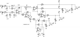
Hello everybody. I managed to modify the wiki adding all the stuff I've been able to gather while working on an EMU0404 of a friend of mine.
He asked me to modify it as some other guys did on the web. While I had it open, I identified some parts.
Hope you'll enjoy
Best,
Simone
p.s. I'm attaching the full post DAC schematic for having an URL for the wiki
He asked me to modify it as some other guys did on the web. While I had it open, I identified some parts.
Hope you'll enjoy
Best,
Simone
p.s. I'm attaching the full post DAC schematic for having an URL for the wiki
Attachments
Hi Simone,
While on my unit the schematic is virtually identical to the one you posted some RefDes and values for the Left channel output are slightly different. Here are the differences I found comparing with mine; you may want to cross-check these:
R290, R268, R307 = 560R
R5 instead of R24, R5 = 22R
C15=68p
C121, C134 = 330p (soundwise the most important difference)
R154, R155 = 2.05k (nominal, just a technicality...)
Also AOL+ & C80 is swapped with AOL- & C81
best
While on my unit the schematic is virtually identical to the one you posted some RefDes and values for the Left channel output are slightly different. Here are the differences I found comparing with mine; you may want to cross-check these:
R290, R268, R307 = 560R
R5 instead of R24, R5 = 22R
C15=68p
C121, C134 = 330p (soundwise the most important difference)
R154, R155 = 2.05k (nominal, just a technicality...
)Also AOL+ & C80 is swapped with AOL- & C81
best
Hi Simone,
While on my unit the schematic is virtually identical to the one you posted some RefDes and values for the Left channel output are slightly different. Here are the differences I found comparing with mine; you may want to cross-check these:
R290, R268, R307 = 560R
R5 instead of R24, R5 = 22R
C15=68p
C121, C134 = 330p (soundwise the most important difference)
R154, R155 = 2.05k (nominal, just a technicality...
Also AOL+ & C80 is swapped with AOL- & C81
best
Hello there.
Well I've just managed to modify the schematic which have been posted by pilli on the wiki. For what regards the output resistor, you're surely right, they're 560R. Creative itself says that in 0404 specs:
Balanced/Unbalanced Output Impedance: 560 Ohms
R24: I've forgot to get the exact name for the left channel so I've just looked over the pics on the web for the name. That's because I don't have the 0404 I've worked on anymore (it's of a friend of mine).
C134: Are you sure about 330pF value? As I said, I can't check that anymore, but I measured 100pF. Will update for C121 anyway
R154,R155: well
C80,C81: maybe pilli just mistyped the two names
Thanks for looking, will update the wiki as soon as I can (I'm morated because I just lurked the forum 'til now. 2 posts and counting anyway
)...talking of different versions, my two units have differences in the top card, the one with all the buttons. One of the two has a blue LED turned inwards (not visible when the card is in the box). The other one has a placeholder marked for a LED diode, but with non components installed.
What do yours look like?
_
What do yours look like?
_
... you may want to cross-check these:
R290, R268, R307 = 560R
R5 instead of R24, R5 = 22R
C15=68p
C121, C134 = 330p (soundwise the most important difference)
R154, R155 = 2.05k (nominal, just a technicality...
Also AOL+ & C80 is swapped with AOL- & C81
Hi sidiy,
thanks for checking these.
Your values for the resistors are right, and also the coupling caps (C80, C81) with the phases of the left channel.
I don't know about the filter C's. Measuring that network in circuit doesn't seem to give me meaningful results; I was a bit surprised of the 100pF that Simone measured... but then, as I said, I don't know about filters
If I get them off of the board I'll measure reliably.
Meanwhile, I am testing with direct coupling of the summing filter, that is with the coupling caps C80, C81, C82, C83 shorted.
This is until now the most notable improvement!
There is definitely better bass, deeper and clearer, and instruments sound smoother, with more space around them.
Sorry for this lingo... not easy to describe without the corny images we've learned.
But remember I am doing A-B comparison with another (unmodified) unit, so the differences are not just from my memory.
The DAC does not seem to suffer from DC coupling.
On one song only, the bass seemed to clip a little bit (a rock piece, maybe too compressed?). Could it be that the 2,5V offset brings the signal swing too close to the positive rail?
Still perplexed...
If it's so easy, why do they put those coupling caps at all...?
-
As I said, I think I mistyped have confused read values in my mind, because I wrote them on a paper which I couldn't find anymore. I thought to remember 100pF, but now it's surely wrong.I was a bit surprised of the 100pF that Simone measured...
Because that's the way to go. Speakers don't "talk" DCIf it's so easy, why do they put those coupling caps at all...?
-
The DAC seems to be biased at 2,5V and that's a standard I think (it's just the 5V typic logical voltages divided by 2). Then there's all those opamps which are biased to GND (0V) thanks to dual voltage supplies. If they'd be just positive supplied (ie Vcc=+12V Vdd=0V, same swing), they would have had DC decoupling caps, because they would have been biased at Vcc/2 (+6V). This way to go is a standard in guitar effects, for example.
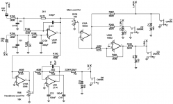
Well anyway here's the updated schematic. Thanks for pointing all those things out sidiy! I'm going to revise the wiki as soon as a mod authorizes my last edit (I'm still moderated as I said. Cmon admins, I ain't no bot/troll )
)Attachments
Hi,
I'm quite sure about the values - measured out of circuit with a pretty good bridge. C110, C140 are 3.3n nominal. The filter is a 2nd order Butterworth, Fc=288.6kHz.
Anyway, I changed mine to a 3rd order Bessel @245kHz...without coupling caps.
The problem when removing these is to make sure that DC loading is not higher than the specified limits. Since the DAC is not supposed to output DC the offset after the filter should be 0V. (the filter is also a BAL to SE converter).
Last edited:
each output on the DAC is riding on a DCoffset equal to Vcom, hence the need for a differential post-DAC filter (it also doubles output voltage swing)
It is very possible to use only a single ended post-DAC, but then you need a DC blocking cap and also a resistive load on the unused DAC out.
As I wrote before, I can not see the use of both to electrolytic caps AND a differential post-DAC. The DC offset is equal to the 2068 offset , more or less within a mV or so.
Away with those filthy caps!
Last edited:
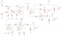
Updated and (final?) schematic
Shouldn't the opamp work bad because of DAC DC offset if we remove caps? It's biased at 0V, it should saturate over the positive supply easily, shouldn't it?The DC offset is equal to the 2068 offset , more or less within a mV or so.
Attachments
that entirely depends on the Vref voltage och the DAC, and also the voltage supply to the OP.
That is a very good point that I didnt consider, perhaps the supply voltage is not sufficient to allow for a DC connection to the DAC output.
What Vref is used?
What voltageswing is allowed by the OP? Perhaps time to check datasheet.
If I read datasheet for AKM4396 correctly a Vref of 5V generates a 2,8 V p-p swing on the DAC out (1,4 V peak) riding on Vcom which is Vdd/2.
This is for analog supply voltage of 5V.
Hence maximum voltage input is 1,4+2,5 = 3,9 V , but the swing on the 2068 output would be 2,8V volts , centered around ground.
Or?
that entirely depends on the Vref voltage och the DAC, and also the voltage supply to the OP.
Just as a double check, I measured what's on the AKM4396 on the EMu 0404, and it is according to the datasheet:
VREFH = 5V
VREFL = 0V
Outputs of the DAC with no signal are at 2,53V.
But then we conclude that the reason for the coupling caps is not the limited headroom on the opamps, since these have +/-6V supply...
Maybe a case of what's called here in france "both belt and suspenders"?
Whatever.
It sounds good without those caps,
the datasheet encourages to do it,
offset out of the filter-summer is just few mV,
so it'll stay without.
(Going differential will be explored later...)
-
- Status
- This old topic is closed. If you want to reopen this topic, contact a moderator using the "Report Post" button.
- Home
- Source & Line
- Digital Line Level
- E-MU 0404 USB Modification?