I had a problem with the left Hi-Z_Line/XLR input, Hi-Z_Line stopped work but the xlr was normal.
I had to troubleshooting how this input works.
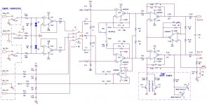
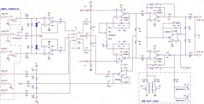
Before time ago a member (sdiy) had done a wonderful work and give us the left-right input schematics. I have enclosed these schematics again.
Unfortunately, sdiy schematics doesn't the information about this.
From what I saw, each input has the auto ability to choice the TRS or XLR plug. Each time to input a TRS plug input to Neutrik pcb plug, a click sound of relay is occurred.
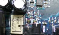
To achieved this, there is a Takamisawa A5W-K relay (each channel) that choice the XLR or TRS plug input. The pin10 of this relay has two modes, Hi (5V) and Lo. The Hi mode choice the XLR input the Lo mode choice the TRS input.
In my situation there was a problem on related transistor that enable Hi or Lo the pin10 of the left relay input.
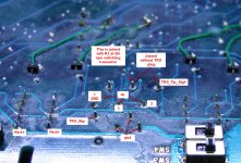
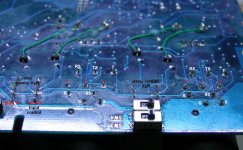
In the attached photo, seems this area and the two tranistors Q4, Q7 with marking 301 Y (probably a fdv301n Fairchild FET) that enable the pin 10 of the two relays, the left transistor for the pin10 of left input relay, the right transistor for the pin10 of right input relay.
Somewhat, there is a communication of Neutrik pcb plug (middle pin) with the resistor (4.7Meg) that enables the transistor Q4 or Q7.
I saw that, if there is no any TRS plug on Neutrik the middle and the upper right pin is connected (the upper right has the Signal + of TRS), but when the TRS inserted into the Neutrik, this connection has gone and only the middle pin is connected to the resistor of transistor.
For now, I hadn't a 301 Y transistor, get out the Q7 transistor and joined the output of these two. Now, the left input works very well, but it needs a TRS plug joined to right Neutrik pcb plug for this reason.
I had to troubleshooting how this input works.
Before time ago a member (sdiy) had done a wonderful work and give us the left-right input schematics. I have enclosed these schematics again.
Unfortunately, sdiy schematics doesn't the information about this.
From what I saw, each input has the auto ability to choice the TRS or XLR plug. Each time to input a TRS plug input to Neutrik pcb plug, a click sound of relay is occurred.
To achieved this, there is a Takamisawa A5W-K relay (each channel) that choice the XLR or TRS plug input. The pin10 of this relay has two modes, Hi (5V) and Lo. The Hi mode choice the XLR input the Lo mode choice the TRS input.
In my situation there was a problem on related transistor that enable Hi or Lo the pin10 of the left relay input.
In the attached photo, seems this area and the two tranistors Q4, Q7 with marking 301 Y (probably a fdv301n Fairchild FET) that enable the pin 10 of the two relays, the left transistor for the pin10 of left input relay, the right transistor for the pin10 of right input relay.
Somewhat, there is a communication of Neutrik pcb plug (middle pin) with the resistor (4.7Meg) that enables the transistor Q4 or Q7.
I saw that, if there is no any TRS plug on Neutrik the middle and the upper right pin is connected (the upper right has the Signal + of TRS), but when the TRS inserted into the Neutrik, this connection has gone and only the middle pin is connected to the resistor of transistor.
For now, I hadn't a 301 Y transistor, get out the Q7 transistor and joined the output of these two. Now, the left input works very well, but it needs a TRS plug joined to right Neutrik pcb plug for this reason.
Attachments
I have looked the Neutrik XLR Combo Dawning and I must update one of two photos.
R = Ring
S = Sleeve
T = Tip
RS is the same with RN in term
TS is the same with TN in term
SS is the same with SN in term
1, 2, 3 = XLR's output
G = Ground
When the phono jack is out from Neutrik, the R+RS, S+SS and T+TS are joined, but when the phono plug is inputting they are off, like a switch.
R = Ring
S = Sleeve
T = Tip
RS is the same with RN in term
TS is the same with TN in term
SS is the same with SN in term
1, 2, 3 = XLR's output
G = Ground
When the phono jack is out from Neutrik, the R+RS, S+SS and T+TS are joined, but when the phono plug is inputting they are off, like a switch.
Attachments
Hi all,
Old thread, but maybe anyone have some pointers on disassembly? The direct monitor level comes off very easily, but the rest don't budge and I feel I'm close to breaking them if I pull any harder. There has to be a shtick to this.
I'm trying to gain access to the parts needing upgrading/rerouting.
Thank you!
---------------------------------------- (5 min later)
GOT IT!
Last edited:
- Status
- This old topic is closed. If you want to reopen this topic, contact a moderator using the "Report Post" button.