[h=Motivation]%2[/h]
I decided to start this wiki to keep track of all info we can find about how to improve the E-MU 0404 USB (and possibly the Tracker Pre) sound interfaces.
Main modification topic is here
[h=Component identification and function]%2[/h]
The contents of this section should be to identify on-board components and their function.
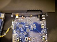
Detailed pics of EMU0404 are HERE
Image of the DAC section
Component identification (pic found on the web, thanks to the guy who made it)
[h=Observations]%3[/h]
* Opamps U5, U16, U33, and U39 get Vcc=6.14V and Vdd=-6.46V. All opamps seem to be on the same rails.
* Vdd on these opamps has nasty high frequency ripple of about 6mV p-p
* Vcc measures about 2mV p-p
* Pin 5 of the TPS6755 supplies the negative voltage Vdd, and has the exact shape ripple seen on the opamp Vdd; interesting that the TPS7655 works at a switching frequency of 160kHz and the ripple frequency seems right about that. If anything, this would be where I'd start, by replacing the Vdd supply.
[h=Power converters]%3[/h]
PHKI = TPS62200DBV IC
* High efficiency sot23 step-down dc-dc converter, 2.5V-6V input, adjustable output 0.7V to 6V, 1MHz PWM
* Datasheet
* Part ID: U42
* Nearby: R310 code 66D is 475K, R313 code 90C is 84.5K
* Vout=0.5 * (1 + R310/R313)=3.31V
* DAC digital supply; also goes to the ADC (AKM5385)
* Part ID: U23
* Nearby: R207 code 26D is 182K, R208 code 66D is 475K
* Vout=0.5 * (1 + R208/R207)=1.82V
* Seems to supply the scary BGA chips...
PHOI = TPS61040DBV IC
* part ID: U10
* Low-power sot23 dc-dc boost converter
* 1.8V-6V input, adjustable output voltage up to 28V
* up to 1MHz switching frequency
* up to 400mA
* nearby: R99 code 39B is 2K49, R97 code 94C is 93K1
* Vout=1.233 * (1 + R97/R99)= 47.33V
* Is this the 48V phantom power??? When the TPS61040 is rated to give only up to 28V? There must be some trick with the nearby MosFet 4850...
* Datasheet
PGVI = TPS73001DBVR IC
* Low-noise, high psrr, RF 200-mA low-dropout adjustable linear regulator
* Vin up to 6V, adjustable output voltage 1.22V-5.5V
* PSRR 68dB at 1kHz, line regulation 0.05 %/V, load regulation 5mV (delta Vout % / delta Iout, up to 200mA), output noise voltage 23uVrms (TPS73018) from 200Hz to 100kHz
* Datasheet
* part ID: U35
* nearby R283 code 94C 93K1, R300 code 47C 30K1
* Vout=1.225 * (1 + R283/R300)=5.01V
* Vin is from U43
* seems to supply the AK4311 chip (digital interface)
* part ID: U25
* nearby R225 code 94C 93K1, R230 code 47C 30K1
* Vout= 1.225 * (1 + R225/R230) &= 5.01V
* Vin is from U43
* DAC Analog supply; also feeds the ADC (AKM5385)
S28B = LM2704 IC
* Part ID: U43
* Micropower step-up dc-dc conveter with 550mA peak current limit
* 2.2V-7V input voltage, up to 20V adjustable output voltage
* Nearby R312 code 01D is 100K, R314 code 243 is 24K
* Vout=1.237 * (1 + R312/R314)= 6.39V
* Positive supply to the Op Amps. Also used as input by some other regulators.
* Datasheet
6755I = TPS6755I IC
* Part ID: U28
* Adjustable invertind dc-dc converter
* Input voltage 2.7V-9V, output voltage limited to Vout≤(12V - Vin)
* 160kHz fixed-frequency PWM controller
* This supplies -6V, the negative rail for the OpAmps
* Datasheet
[h=Opamps]%3[/h]
* Note: In the Emu 0404 usb the opamps get +/- 6V on pins 4-8; but the levels don't seem very symmetric (+6.2V;-6.0V).
* Note: In the Emu 0404 2.0 (White edition) levels are not symmetric too, but they're a bit different (+6.0V;-6.3V)
15532=NE5532 (?)
* Part ID: U1, U2, many others
* Internally compensated for gain 1
* Slew rate 8V/uS, en 8nV/sqrtHz, GB 10MHz, Vo 5mV
* Possible replacement AD8599, en 1nV/sqrtHz, Vo 10uV, GB 10MHz, slew rate 16V/uS, thd -105dB or 0.00000056
* Datasheet
2068=JRC2068=NJM2068
* Part ID: many
* Unity gain bandwidth
* THD 0.001%
* Slew rate 6V/uS
* Datasheet
2114=JRC NJM2114
* Part ID: U5
* Headphone driver opamp
* Datasheet
[h=Other]%3[/h]
4850 IC
* Near inductor of U10 PHOI
* N-Channel power MOSFET.
* Used with the DC/DC converter U10.
* Datasheet
15D diodes
* Transient Voltage Suppression diodes
* Each input and output line has one of these
* Succesfully substituted with 1N914 diodes in series (see datasheet for pinout)
* Datasheet
OWNK Muting N-JFET transistors
* Each output line goes through one of these components marked "OWNK" (couldn't find this reference anywhere)
* Found out the purpose of these: they mute lines when board turns on!
* No change in voltages on pins when changing Direct Out mode
* Sources are all wired to GND while drains are wired to line output
* Gates seems to be supplied by negative voltage (varies between -5.5V to -3V in different measures). At startup this goes to +4V. Immediatly after it drops to the negative voltage above
* If you're getting VERY low output volume, most likely these are burnt. Just unsolder them and it will work like never before (plus you'll get rid of some parasitic capacitance)
[h=Post DAC Output Stage]%3[/h]
The output stage has a summing filter first (opamp U22), very similar to what's given in the AK4396 datasheet. This is followed by a volume potentiometer, then a buffer (opamp U32).
The output of the buffer goes to the output jacks and also to another opamp (U39), in inverting unity amplifier configuration, that produces the inverted output for the balanced (!!) TRS
output jacks. Shown are left channel circuitry through main and headphone out. Diodes and JFETs other than the HP out aren't labeled with the right PCB name.
Schematic:
(Right channel takes the "B" of each opamp.)
Eagle 6.1.0 Schematic file
Original schematic drawn by pilli
[h=Mod categories]%2[/h]
[h=Power supply]%3[/h]
Filter Capacitors
You can swap out some of the filtering caps and putting new higher valued ones. This will (maybe) improve filtering. The DC/DC converters present in the PCB doesn't seem
to allow much changing in value though. Going too much up with value, will bring in an endless reset loop of the EMU.
Basically what you can do is:
* Change the 3x10uF supply filtering caps near the 4 above with higher valued caps. Somebody reports 470uF to be the maximum accettable value which won't make the board unstable (reset loop)
ADDITIONAL NOTE: it seems that even 220uF value will make the board unstable, especially when EMU has been turned on for long periods. 100uF may be a good value (it's 10 times bigger than original, anyway)
* Change the big 100uF 63V cap (seems to be orange in EMU0404 1st model, not the white one) with something higher (I put 220uF). Keep in mind that this is for 48V, so you'd
better swap it with 63V still.
Don't even give a try changing the 2x220uF near U5 HP driver, because 470uF will make the board unstable.
Output stage Op Amps supply
An "easy" thing to do is to provide a linear regulated ±6V supply for the output stage opamps (U22, U16, U33, U39) with a dedicated power supply.
The ±6V rails reach the opamps through two jumper 0 Ohm resistors, components R149 and R157. If you remove these two, you can attach a new ±6V supply.
It is too tricky to solder on these tiny pads though. You'd better use the two local capacitors C103 and C109 pads, which are through-hole electrolytics. You'll need to attach your ground nearby on a pad nearby too.
Notice that the headphone driver U5 receives the same rails but through two other resistors, that are 1 Ohm, R83 and R74. These are larger, of course, because that's a low impedance driver (headphone). These have local elcos too, C30 and C39.
NOTE: ±6V seems a bit low. I would try ±12V.
Personally I wouldn't mind this mod because DAC resolution is fixed. Having higher supply voltages over opamps will give better resolution for the opamps themselves. But then, the wave coming from the DAC will still have AKM5385 resolution. As pilli told me in a PM, using ±9V didn't gave him much results (needs to be confirmed) (FixMetal)
Linear regulated +5V PSU
The other common mod is to create a linear regulated PSU with a 7805 and some bypass transistor. Note that you'll have to dissipate a great amount of heat. Some pics on the
web shows a fan over a heatsink for getting more heat out of it, but that way will most likely inject fan noise into your board (because of DC motor supplied by your regulator).
Keep in mind that you'll need a (at least) 1.2A transformer and a 12000uF input filtering capacitance to get a 5% ripple before the regulator. Spike smoother caps on the
diode bridge will surely improve the thing.
This mod won't (of course) eliminate the side effect of frequencies injected by DC-DC converters INSIDE the board. You should note that if the 160KHz (as supposed above) is the dominant noise in this board, it's 8 times over the audiable threshold! Even harmonics will go UP to 160KHz, not down, so there's really no chance for you to ear this (not even for your dog, I swear)
[h=Opamps]%3[/h]
Not every opamp seem to be a good compromise being replaced instead of the original ones. I tried LT1364 in place of U33 and all I obtained was short between Vcc and OutB of the opamp. Same as above, I couldn't change U3 nor U7 with NE5532 without having HUGE pops, crackles and s**t over the 2 inputs too. There must be some decoupling/bias stuff that won't let some higher spec opamp work well.
[h=DAC Decoupling caps]%3[/h]
It is up to you to decide wheter get rid of these or just raise the value . Many says that without these caps you get a better bass response and a more organic overall sounding board. The fact is you'd inject some DC into your speakers. BUT, there's a but. Since the EMU can't handle passive speakers, any that you will use will have some electronic between the board and the speaker itself, making your line out signal strong enough to drive the speaker. Any of these electronic stuff has surely a DC decoupling capacitor before whatever the signal goes in. Actually you don't really have to think about DC being injected into speaker.
If you're not enthusiast with this, you can always replace the 4x47uF decoupling caps with higher valued ones, like 220uF.
[h=Fixing left channel peaks]%3[/h]
For somewhat reason Creative made a layout with lines prone to DC-DC converter and USB datarate noise. The left channel line is near an inductor, which of course induces noise to the line. Thanks to Sidiy on the forum, there's a fix for this. Instructions goes like Sidiy had
this done. Topic's here and here
Traces shown
Step-by-step mod
Note: be very gentle while lifting the two resistors as the pads are real weak
I decided to start this wiki to keep track of all info we can find about how to improve the E-MU 0404 USB (and possibly the Tracker Pre) sound interfaces.
Main modification topic is here
[h=Component identification and function]%2[/h]
The contents of this section should be to identify on-board components and their function.
Detailed pics of EMU0404 are HERE
Image of the DAC section
An externally hosted image should be here but it was not working when we last tested it.
Component identification (pic found on the web, thanks to the guy who made it)
An externally hosted image should be here but it was not working when we last tested it.
[h=Observations]%3[/h]
* Opamps U5, U16, U33, and U39 get Vcc=6.14V and Vdd=-6.46V. All opamps seem to be on the same rails.
* Vdd on these opamps has nasty high frequency ripple of about 6mV p-p
* Vcc measures about 2mV p-p
* Pin 5 of the TPS6755 supplies the negative voltage Vdd, and has the exact shape ripple seen on the opamp Vdd; interesting that the TPS7655 works at a switching frequency of 160kHz and the ripple frequency seems right about that. If anything, this would be where I'd start, by replacing the Vdd supply.
[h=Power converters]%3[/h]
PHKI = TPS62200DBV IC
* High efficiency sot23 step-down dc-dc converter, 2.5V-6V input, adjustable output 0.7V to 6V, 1MHz PWM
* Datasheet
* Part ID: U42
* Nearby: R310 code 66D is 475K, R313 code 90C is 84.5K
* Vout=0.5 * (1 + R310/R313)=3.31V
* DAC digital supply; also goes to the ADC (AKM5385)
* Part ID: U23
* Nearby: R207 code 26D is 182K, R208 code 66D is 475K
* Vout=0.5 * (1 + R208/R207)=1.82V
* Seems to supply the scary BGA chips...
PHOI = TPS61040DBV IC
* part ID: U10
* Low-power sot23 dc-dc boost converter
* 1.8V-6V input, adjustable output voltage up to 28V
* up to 1MHz switching frequency
* up to 400mA
* nearby: R99 code 39B is 2K49, R97 code 94C is 93K1
* Vout=1.233 * (1 + R97/R99)= 47.33V
* Is this the 48V phantom power??? When the TPS61040 is rated to give only up to 28V? There must be some trick with the nearby MosFet 4850...
* Datasheet
PGVI = TPS73001DBVR IC
* Low-noise, high psrr, RF 200-mA low-dropout adjustable linear regulator
* Vin up to 6V, adjustable output voltage 1.22V-5.5V
* PSRR 68dB at 1kHz, line regulation 0.05 %/V, load regulation 5mV (delta Vout % / delta Iout, up to 200mA), output noise voltage 23uVrms (TPS73018) from 200Hz to 100kHz
* Datasheet
* part ID: U35
* nearby R283 code 94C 93K1, R300 code 47C 30K1
* Vout=1.225 * (1 + R283/R300)=5.01V
* Vin is from U43
* seems to supply the AK4311 chip (digital interface)
* part ID: U25
* nearby R225 code 94C 93K1, R230 code 47C 30K1
* Vout= 1.225 * (1 + R225/R230) &= 5.01V
* Vin is from U43
* DAC Analog supply; also feeds the ADC (AKM5385)
S28B = LM2704 IC
* Part ID: U43
* Micropower step-up dc-dc conveter with 550mA peak current limit
* 2.2V-7V input voltage, up to 20V adjustable output voltage
* Nearby R312 code 01D is 100K, R314 code 243 is 24K
* Vout=1.237 * (1 + R312/R314)= 6.39V
* Positive supply to the Op Amps. Also used as input by some other regulators.
* Datasheet
6755I = TPS6755I IC
* Part ID: U28
* Adjustable invertind dc-dc converter
* Input voltage 2.7V-9V, output voltage limited to Vout≤(12V - Vin)
* 160kHz fixed-frequency PWM controller
* This supplies -6V, the negative rail for the OpAmps
* Datasheet
[h=Opamps]%3[/h]
* Note: In the Emu 0404 usb the opamps get +/- 6V on pins 4-8; but the levels don't seem very symmetric (+6.2V;-6.0V).
* Note: In the Emu 0404 2.0 (White edition) levels are not symmetric too, but they're a bit different (+6.0V;-6.3V)
15532=NE5532 (?)
* Part ID: U1, U2, many others
* Internally compensated for gain 1
* Slew rate 8V/uS, en 8nV/sqrtHz, GB 10MHz, Vo 5mV
* Possible replacement AD8599, en 1nV/sqrtHz, Vo 10uV, GB 10MHz, slew rate 16V/uS, thd -105dB or 0.00000056
* Datasheet
2068=JRC2068=NJM2068
* Part ID: many
* Unity gain bandwidth
* THD 0.001%
* Slew rate 6V/uS
* Datasheet
2114=JRC NJM2114
* Part ID: U5
* Headphone driver opamp
* Datasheet
[h=Other]%3[/h]
4850 IC
* Near inductor of U10 PHOI
* N-Channel power MOSFET.
* Used with the DC/DC converter U10.
* Datasheet
15D diodes
* Transient Voltage Suppression diodes
* Each input and output line has one of these
* Succesfully substituted with 1N914 diodes in series (see datasheet for pinout)
* Datasheet
OWNK Muting N-JFET transistors
* Each output line goes through one of these components marked "OWNK" (couldn't find this reference anywhere)
* Found out the purpose of these: they mute lines when board turns on!
* No change in voltages on pins when changing Direct Out mode
* Sources are all wired to GND while drains are wired to line output
* Gates seems to be supplied by negative voltage (varies between -5.5V to -3V in different measures). At startup this goes to +4V. Immediatly after it drops to the negative voltage above
* If you're getting VERY low output volume, most likely these are burnt. Just unsolder them and it will work like never before (plus you'll get rid of some parasitic capacitance)
[h=Post DAC Output Stage]%3[/h]
The output stage has a summing filter first (opamp U22), very similar to what's given in the AK4396 datasheet. This is followed by a volume potentiometer, then a buffer (opamp U32).
The output of the buffer goes to the output jacks and also to another opamp (U39), in inverting unity amplifier configuration, that produces the inverted output for the balanced (!!) TRS
output jacks. Shown are left channel circuitry through main and headphone out. Diodes and JFETs other than the HP out aren't labeled with the right PCB name.
Schematic:
An externally hosted image should be here but it was not working when we last tested it.
(Right channel takes the "B" of each opamp.)
Eagle 6.1.0 Schematic file
Original schematic drawn by pilli
[h=Mod categories]%2[/h]
[h=Power supply]%3[/h]
Filter Capacitors
You can swap out some of the filtering caps and putting new higher valued ones. This will (maybe) improve filtering. The DC/DC converters present in the PCB doesn't seem
to allow much changing in value though. Going too much up with value, will bring in an endless reset loop of the EMU.
Basically what you can do is:
* Change the 3x10uF supply filtering caps near the 4 above with higher valued caps. Somebody reports 470uF to be the maximum accettable value which won't make the board unstable (reset loop)
ADDITIONAL NOTE: it seems that even 220uF value will make the board unstable, especially when EMU has been turned on for long periods. 100uF may be a good value (it's 10 times bigger than original, anyway)
* Change the big 100uF 63V cap (seems to be orange in EMU0404 1st model, not the white one) with something higher (I put 220uF). Keep in mind that this is for 48V, so you'd
better swap it with 63V still.
Don't even give a try changing the 2x220uF near U5 HP driver, because 470uF will make the board unstable.
Output stage Op Amps supply
An "easy" thing to do is to provide a linear regulated ±6V supply for the output stage opamps (U22, U16, U33, U39) with a dedicated power supply.
The ±6V rails reach the opamps through two jumper 0 Ohm resistors, components R149 and R157. If you remove these two, you can attach a new ±6V supply.
It is too tricky to solder on these tiny pads though. You'd better use the two local capacitors C103 and C109 pads, which are through-hole electrolytics. You'll need to attach your ground nearby on a pad nearby too.
Notice that the headphone driver U5 receives the same rails but through two other resistors, that are 1 Ohm, R83 and R74. These are larger, of course, because that's a low impedance driver (headphone). These have local elcos too, C30 and C39.
NOTE: ±6V seems a bit low. I would try ±12V.
Personally I wouldn't mind this mod because DAC resolution is fixed. Having higher supply voltages over opamps will give better resolution for the opamps themselves. But then, the wave coming from the DAC will still have AKM5385 resolution. As pilli told me in a PM, using ±9V didn't gave him much results (needs to be confirmed) (FixMetal)
Linear regulated +5V PSU
The other common mod is to create a linear regulated PSU with a 7805 and some bypass transistor. Note that you'll have to dissipate a great amount of heat. Some pics on the
web shows a fan over a heatsink for getting more heat out of it, but that way will most likely inject fan noise into your board (because of DC motor supplied by your regulator).
Keep in mind that you'll need a (at least) 1.2A transformer and a 12000uF input filtering capacitance to get a 5% ripple before the regulator. Spike smoother caps on the
diode bridge will surely improve the thing.
This mod won't (of course) eliminate the side effect of frequencies injected by DC-DC converters INSIDE the board. You should note that if the 160KHz (as supposed above) is the dominant noise in this board, it's 8 times over the audiable threshold! Even harmonics will go UP to 160KHz, not down, so there's really no chance for you to ear this (not even for your dog, I swear)
[h=Opamps]%3[/h]
Not every opamp seem to be a good compromise being replaced instead of the original ones. I tried LT1364 in place of U33 and all I obtained was short between Vcc and OutB of the opamp. Same as above, I couldn't change U3 nor U7 with NE5532 without having HUGE pops, crackles and s**t over the 2 inputs too. There must be some decoupling/bias stuff that won't let some higher spec opamp work well.
[h=DAC Decoupling caps]%3[/h]
It is up to you to decide wheter get rid of these or just raise the value . Many says that without these caps you get a better bass response and a more organic overall sounding board. The fact is you'd inject some DC into your speakers. BUT, there's a but. Since the EMU can't handle passive speakers, any that you will use will have some electronic between the board and the speaker itself, making your line out signal strong enough to drive the speaker. Any of these electronic stuff has surely a DC decoupling capacitor before whatever the signal goes in. Actually you don't really have to think about DC being injected into speaker.
If you're not enthusiast with this, you can always replace the 4x47uF decoupling caps with higher valued ones, like 220uF.
[h=Fixing left channel peaks]%3[/h]
For somewhat reason Creative made a layout with lines prone to DC-DC converter and USB datarate noise. The left channel line is near an inductor, which of course induces noise to the line. Thanks to Sidiy on the forum, there's a fix for this. Instructions goes like Sidiy had
this done. Topic's here and here
Pic of the areaThe fix is obvious.
1. Lift R151 and R167
2. Cut the traces near the pads of R123 and R128 as shown, making sure not to go too deep or to chip some neighboring components.
3. Solder a pair of wires, twisted a couple of times, to rework the connection. On the right side I chose the pads of R108 and R110 which belong to the same original nodes while for the left side I used the leftmost pads of R151 and R167. I did not want to pass the wires over the ADC to C101, not optimal in my opinion. Make sure not to reverse the phase.
An externally hosted image should be here but it was not working when we last tested it.
Traces shown
An externally hosted image should be here but it was not working when we last tested it.
Step-by-step mod
An externally hosted image should be here but it was not working when we last tested it.
An externally hosted image should be here but it was not working when we last tested it.
An externally hosted image should be here but it was not working when we last tested it.
Note: be very gentle while lifting the two resistors as the pads are real weak
Last edited by a moderator:
A few issues around this and the 0202 and Tracker Pre- first the Windows driver has not been changed since 2008 and doesn't work properly with Windows 7 (so far). Second, they seem to have constrained the digital output to a max of 96K with no obvious reason why. I don't have an 0404 so I can't test to see what happens at the 176 and 192 sample rates.
There is support in Linux/ALSA for the EMU usb cards, and I expect it will be more stable than EMU's drivers are reputed to be.
I hope worthwhile imporvements can be made since these are available and reasonably priced.
There is support in Linux/ALSA for the EMU usb cards, and I expect it will be more stable than EMU's drivers are reputed to be.
I hope worthwhile imporvements can be made since these are available and reasonably priced.
I had more success with the Windows driver on Win 7 when I figured out that there are several places to set the sample rate. The whole think is really kludgey compared to XP.
However the 0404 specs say the max sample rate from the digital outputs is 96K (not the 192K possible internally). modifying the power supplies will help a lot since the internal clocks are sensitive to noise.
However the 0404 specs say the max sample rate from the digital outputs is 96K (not the 192K possible internally). modifying the power supplies will help a lot since the internal clocks are sensitive to noise.
Hello everybody!
Need Help!
I have an EMU 0404. I put power supply 19VDC for the EMU 0404 and the results are a visual IC U10 (TPS61040=PHOI) was burned black.
In my country, i can't buy U10 IC because i don't know how to do.
Please, show me how to repair it.
There is absolutely no need to replace the stock 5V smps, as anyway there are a number of smps converters inside the board that will get higher and negative voltages out of the 5V.
In any case, replace U10 and the supporting resistors around it (possibly there will be some capacitors there too). Check the parts leading to U10 and after it too.
Hi,
I would be very interested to see photos of the pcb in the article. It will ease understanding and help choosing this platform for mods.
I am thinking of removing all regulators and replace them by good ones, that is no switching regulators. It should be even possible to put batteries for some portions (li po seems to be the buzz).
Can we see the clock ? Is it possible to uprgade it with good ones ?
Thanks for your work and attention.
Lwi.
Hey Guys,
I bought an E-MU 0404 usb, and I want to mod it, but, I I'm not an electrician kinda person, let's say total noob, don't have the knowledge for it. So, is there anyone, who would do that for me for some bucks? I live in London by the way.
Thanks in advance,
Zoltan
neoyoli at gmail dot com
I bought an E-MU 0404 usb, and I want to mod it, but, I I'm not an electrician kinda person, let's say total noob, don't have the knowledge for it. So, is there anyone, who would do that for me for some bucks? I live in London by the way.
Thanks in advance,
Zoltan
neoyoli at gmail dot com
I discovered some more stuff to be added in the wiki.
I traced the entire post DAC section (HP included). The muting trannies which are in output sections are possibly n channel jfet, but they are not really of much help. Plus they seems to be a weak point. I got an EMU0404 which showed uber low output on any jack and it was all jfet's fault. Once I removed them, I got back the sound.
Hope mod will open the wiki again for editing (I added some stuff, still in approval though).
Best,
Simone
Hi guys.
Is it possible to drive signal from DAC chip (pins 20.-23.) directly to preamplifier, or it's necessary to add some kind of buffer?
Having a real schematic would be very helpful.
Thanks
Just updated (and fixed links) of the wiki. Check it out
")
New mods and measurements (mainly ADC)
Hi all, following this thread since I bought one 3 years ago, only just soldered a power supply and hooked it up for the 1st time (busy with other things...).
After struggling a lot with USB drivers, the 1.40 beta drivers seem to work flawlessly now on AMD Win7 64-bit. So now I can start modding.
Timing is perfect as there is renewed interest from others as well. Fellow member misterzu has been upgrading mainly the input side, done before/after measurements, with a full description and schematics, and it looks really good.
Look here:
Things get interesting from page 13 onwards, summary is on pages 18/19.
Probably I'll be back with questions later
Hi all, following this thread since I bought one 3 years ago, only just soldered a power supply and hooked it up for the 1st time (busy with other things...).
After struggling a lot with USB drivers, the 1.40 beta drivers seem to work flawlessly now on AMD Win7 64-bit. So now I can start modding
. Timing is perfect as there is renewed interest from others as well. Fellow member misterzu has been upgrading mainly the input side, done before/after measurements, with a full description and schematics, and it looks really good.
Look here:
Things get interesting from page 13 onwards, summary is on pages 18/19.
Probably I'll be back with questions later
A problem from power supply
Dear all,
I put a 12V power supply (instead of 5 V DC) by mistake and since then it's not working.
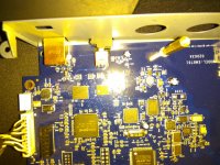
I opened it and it died an internal U42 component which u can see in the picture at the position circled in RED.
i would be grateful if you could tell me what's this component so i can replace it, i guess it's a voltage distribute .
Thank you very much for your time,
George
Dear all,
I put a 12V power supply (instead of 5 V DC) by mistake and since then it's not working.
I opened it and it died an internal U42 component which u can see in the picture at the position circled in RED.
i would be grateful if you could tell me what's this component so i can replace it, i guess it's a voltage distribute .
Thank you very much for your time,
George
Attachments
Last edited:
- Status
- This old topic is closed. If you want to reopen this topic, contact a moderator using the "Report Post" button.
- Home
- diyaudio.com Wiki
- E-MU 0404 USB mod wiki