And the fact that the line is shorted by the opposite amplifier?
dual voice coil speakers? L into one VC and R into the other? in results two separated circuits for L and R amplifier?
good solution? feasible in 1971?
Perhaps you should explain the theory of how it works since I've expressed the view that it can't.
David S.
to be precise You have expressed the view that a notional diagram is a notional diagram and I have expressed the view that You are right on this point
it' beyond dispute that a notional diagram is a notional diagram

agreed?
And why would he show such an obviously flawed "notional diagram" if he had built the real thing and worked out the bugs?
Dual voice coil would seperate the DC path but not totally remove the cross coupling. Plus, if dual voice coil was his solution, wouldn't he have mentioned it and drawn it?
His description to me sound very vague as if he thought it would be a good idea but had never worked out the details. It would be nice to have a real description, drawing or picture of what he supposedly made. If it performed as well as you suppose, wouldn't it be written up in some scientific journal?
David S.
If I can offer a couple of thoughts:
I would assume that the drivers were connected in series/parallel so that a sensible impedance would be presented to the amplifier.
My understanding of the horizontal array is that it was grouped as two speakers - i.e. the two stereo channels weren't connected to each other (and so creating a short).
It could also be that Ted Jordan was being deliberately sketchy about the details. They were intended for custom installation rather than a commercial product available in shops. The simple inductor delay line may be an analogy rather than an exact representation as I don't suppose he'd want everyone copying it.
I do remember seeing an advert from the period in either Wireless World or Hi Fi News where his company at the time was offering to instal the system.
You couldn't series/parallel because that would defeat the requirement of a sequential delay line.
Two speakers would be a different case and more feasible, but he clearly didn't draw it that way.
The simple inductor delay line is a bit too simple: it doesn't work. Inductors give trivial delay relative to the significant amount of HF rolloff.
People seem to be going to great lengths to give Jordon the benefit of a doubt: he "didn't draw the real network", "it was 2 seperate lines", "maybe he used dual voice coils" (but its not drawn that way).
It seems to me the simpler answer is that he had a seemingly plausible but unworkable concept that made for interesting reading in a popular magazine article. If, on the other hand, it is a brilliant and workable concept, where is the modern implementation? Where are the subsequent technical papers analyzing the rightness of his theory? Where are the commercial examples of it? Where is the modern evolution of it?
Perhaps there was a grand conspiracy to buy them up and bury them?
David S.
yes, not totally - agreed - but sufficiently, effectively perhaps?Dual voice coil would seperate the DC path but not totally remove the cross coupling.
yes, I agreeYou couldn't series/parallel because that would defeat the requirement of a sequential delay line.
yes, furthermore the description is unambiguous: "a continuous line of speakers ... and the left and right channels are fed in at each end"Two speakers would be a different case and more feasible, but he clearly didn't draw it that way.
The simple inductor delay line is a bit too simple: it doesn't work. Inductors give trivial delay relative to the significant amount of HF rolloff.
yes, but it could be ESL-63 type of delay network
after all Walker invention was based on earlier patents (ESL63History), which were obviously known also to Jordan
so
well, I think that Colin gave the answer:why would he show such an obviously flawed "notional diagram" if he had built the real thing and worked out the bugs?
It could also be that Ted Jordan was being deliberately sketchy about the details. They were intended for custom installation rather than a commercial product available in shops. The simple inductor delay line may be an analogy rather than an exact representation as I don't suppose he'd want everyone copying it.
so
andHis description to me sound very vague as if he thought it would be a good idea but had never worked out the details. It would be nice to have a real description, drawing or picture of what he supposedly made. If it performed as well as you suppose, wouldn't it be written up in some scientific journal?
andIf, on the other hand, it is a brilliant and workable concept, where is the modern implementation? Where are the subsequent technical papers analyzing the rightness of his theory? Where are the commercial examples of it? Where is the modern evolution of it?
the simpler answer is that he had a seemingly plausible but unworkable concept that made for interesting reading in a popular magazine article.
well I think that this simple answer cannot be correct because Jordan would not advertise an inexistent product and:
I do remember seeing an advert from the period in either Wireless World or Hi Fi News where his company at the time was offering to instal the system.
therefore I believe that the answer must be different, I believe that it was indeed a work in progress, but it was real and it was good enough to be custom installed, custom installed only because it was more pricey at the particular stage of it's development than Jordan expected it to be and first of all because it was not one-size-fits-all, it really required matching with the particular room and also it required leaving adjacent parts of the side-walls basically reflective (just as Keele's CBTs require this)
I also suppose that Jordan was thinking about a patent application - exactly therefore the published descriptions were sketchy and probably a bit misleading - I think that the invention was similar to QUAD's delay lines for ESL. Unfortunately (for Jordan) Walker was faster, got His patent first and perhaps disclosed in it some essential elements of the patent application that Jordan was preparing, so they lost their novelty
this could be one of the reasons that eventually persuaded Jordan to discontinue the project
perhaps not the most important reason because first of all no system that has to be custom installed has great commercial potential on the consumer market and Jordan was never a clever marketing type businessman
He was just an old fashioned engineer who had left the mainstream
looks like even an even more interesting article by EJJ was published in the next issue of WW in March 1971, titled "Multiple-array loudspeaker system"
it appears as reference in several patents and in some papers, I have found this PDF for example: http://www.jstage.jst.go.jp/article/ast/27/6/354/_pdf
"Single box surround sound" Acoustical Science and Technology Vol. 27 (2006), No. 6, pp. 354-360
ps.
and here is an explanation of demise of delay line system project from EJJ web page:
http://www.ejjordan.co.uk/ted/present.html
it appears as reference in several patents and in some papers, I have found this PDF for example: http://www.jstage.jst.go.jp/article/ast/27/6/354/_pdf
"Single box surround sound" Acoustical Science and Technology Vol. 27 (2006), No. 6, pp. 354-360
ps.
and here is an explanation of demise of delay line system project from EJJ web page:
Accurate stereo imagery is something of an obsession of Ted's. Without it, he does not feel the full scale and impact of a musical performace is captured. His early experiments involved a continual line of drivers, running horizontally across the wall. This gave tremendous realism and power handling but was rather expensive solution.
http://www.ejjordan.co.uk/ted/present.html
Last edited:
Interesting thread. As noted, Walker described an end fed stereo delay line array in his original paper in Wirelss World. The implementation may just about work with an electrostatic array, utlizing the self capacitance of each panel, but from my modeling doesn't really give sufficient delay for the required 30 degree intended angle.
Doing it with discrete moving coil drivers with series inductors most certainly does not model a sequential delay line with flat frequency response and frequency independant delay.
As to the principal of it simulating a pair of horizontal line souces each angled back by 30 degrees to give an illusion of stereo independat of listener location, even this doesn't work in practice. I tried it using a pair of BG ribbons, 6' long, layed horizontal and angled backwards. Because even a 6' ribbon is not even close to being a true line source, the results were extremely disapointing. Imaging was not very stable with listener location, no matter how I crossed the two ribbons, and sound balance was heavily dependent upon listener location, again because of the characteristic if limited length "quasi-line" sources.
Andrew
I think you would have had to have sat in the middle just about inbetween the X'd ribbons, since you would have had to cross them to get the full effect, you'd have only 3 feet sticking out, so these would have been large nearfield monitors to say the least...
The problem may have been related to being too far back... or not.
_-_-bear
The problem may have been related to being too far back... or not.
_-_-bear
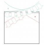
As to the principal of it simulating a pair of horizontal line souces each angled back by 30 degrees to give an illusion of stereo independat of listener location, even this doesn't work in practice. I tried it using a pair of BG ribbons, 6' long, layed horizontal and angled backwards.
I think this is not an adequate simulation - two different directivity patterns
on the scheme below green lines represent the horizontal delay line effect and red lines represent horizontal long ribbon, I mean narrow line source (I know I know B-G is not real ribbon)
I think you would have had to have sat in the middle just about inbetween the X'd ribbons, since you would have had to cross them to get the full effect
exactly! furthermore - and to angle them into a bow-like shape
The problem may have been related to being too far back... or not.
perhaps rather to obviously not being across the (near) full width of the room and not being crossed and angled
Attachments
Hmmm... So Andrew J agrees that inductor linked drivers will not constitute a delay line: "Doing it with discrete moving coil drivers with series inductors most certainly does not model a sequential delay line with flat frequency response and frequency independant delay." (clever fellow!) (emphasis gleefully added by me.)
He also found the performance with crossed line arrays was unimpressive. Note that the poor performance of a too short line array that Andrew experienced would be shared by the Jordan array (assuming it worked as advertised). Without proper tapering a short line section will have highly variable frequency along its length. In addition a line based on multiple full range drivers suffers from alliasing effects which create numerous response lobes. This would be especially bad if the line were a series of, say, 8" drivers. See my paper on the subject or the excellent One Limited paper you referenced above.
AES E-Library Discrete-Element Line Arrays-Their Modeling and Optimization
http://www.jstage.jst.go.jp/article/ast/27/6/354/_pdf
I will offer you a possibility on what Jordan could have designed: If rather than a delay line he just cascaded the drivers with high inductance (high enough to cause in-band rolloff) then he would have had a variable length line or a line with tapered drive. Doing it properly the top Octave would come from the first driver only (on each end). The Octaves below would progressively bring in more of the line length to the point where bass frequencies would bring in most of the drivers across the line. I say "most of the drivers" because you still have the opposite amplifier shorting the line from the far side. You would have to have enough resistance in each choke that the short wouldn't matter. I.e. the bass would also diminish across the line, but to less a degree than the upper range would.
This could work as a sytem and would give a left/right sound source and most of the LF output capibility that Jordan talks about. It just wouldn't work the way he described it. It would not be a delay line driven array.
Regards,
David
He also found the performance with crossed line arrays was unimpressive.
excuse me - what crossed line arrays?
Without proper tapering a short line section will have highly variable frequency along its length.
? why short? according to Jordan the line was to extend across the width of the room
and why do You assume lack of proper tapering?
In addition a line based on multiple full range drivers suffers from alliasing effects which create numerous response lobes. This would be especially bad if the line were a series of, say, 8" drivers.
why 8''? Jordan Watts modules were 4'' maximum
the excellent One Limited paper you referenced above.
which one?
It would not be a delay line driven array.
correct, but what was actually built was a delay line driven array
notwithstanding the fact that You don't know how it was achieved
Is it tapering or is it sequential delay? It won't be both, make up your mind.
Driver spacing (center to center) is the key rather than diameter. He shows an array with 20 units across the width of the room. That gives a point density that will lead to considerable lobing.
David S.
Driver spacing (center to center) is the key rather than diameter. He shows an array with 20 units across the width of the room. That gives a point density that will lead to considerable lobing.
David S.
Is it tapering or is it sequential delay? It won't be both, make up your mind.
cannot be both? just one suffices? what's the problem? In Keele's CBTs there is both shading and delay
Driver spacing (center to center) is the key rather than diameter. He shows an array with 20 units across the width of the room. That gives a point density that will lead to considerable lobing.
it was just a notional diagram ... what's the problem? I thought it was beyond dispute...
So in 1971, without the benefit of computers, Jordan had an array as sophisticated as Keele's CBT. He should have written it up as he was way ahead of his time.
If he used the considerable rolloffs that I suggested, there would be no need of delay to the far elements. You'll need to take my word on this since I have modeled, built and sold such units. In the end, two people that know about such things have told you that what he has drawn can not be an effective delay line.
By notional diagram I always meant a sketch of something that might be neat if it worked. This is not the same as a simplified diagram of a real design. My assumption is that, since the errors in the diagram are considerable and insurmountable, that it was purely a notion.
David
So in 1971, without the benefit of computers, Jordan had an array as sophisticated as Keele's CBT. He should have written it up as he was way ahead of his time.
perhaps even more sophisticated?
quite sophisticated mathematics and physics predate computers by a long, long time
OTOH computers cannot substitute for deficient mind devoid of imagination and creativity
yes He was indeed way ahead of his time - and in many respects, for example He pioneered also the "transmission line driver" idea in the 60s (even before Ohm with their Walsh driver) and now this approach is represented not only by hi-end Manger and German Physiks DDD drivers but also by increasingly popular "Balanced Mode Radiator"-type drivers which are based on Jordan's ideas realized for the first time in the 60s in the Jordan-Watts Module
so yes - He was indeed 40-50 years ahead of His time - are You jealous?
In the end, two people that know about such things have told you that what he has drawn can not be an effective delay line.
Do you need a third one ?????
Maybe you should be more clear. The use of a computer in this case would not be to model and calculate the delay lines (such things have indeed be done before) but to GENERATE the necessary delay(s). It is that huge that is is simply impossible to do it reasonably in the analog fashion. While it is nowadays a piece of cake for even cheap digital circuitry.
OTOH I have read about such systems by the end of the seventies (was it in the magazine "Funkschau"?). I assume that the idea was indeed the use of delay lines but the practical implementation was using lowpass filtering I am convinced (and maybe even an active implementation of this).
Maybe it would even work quite well from the sonical point of view - who knows without trying ?
I know of someone who did an even simpler solution for a small PA in a theatre. He said that he used a matrix to add the left an right signals to the four or five amp channels that were feeding speakers above the front row. I have never heard the sytem though, so I can't judge how well it actually worked.
Regards
Charles
looks like even an even more interesting article by EJJ was published in the next issue of WW in March 1971, titled "Multiple-array loudspeaker system"
it appears as reference in several patents and in some papers, I have found this PDF for example: http://www.jstage.jst.go.jp/article/ast/27/6/354/_pdf
"Single box surround sound" Acoustical Science and Technology Vol. 27 (2006), No. 6, pp. 354-360
I had a personal demo of the 1 Limited unit given by Tony Hooley. It was later marketed by Pioneer for $50,000 (at least you only had to buy one!)
http://www.jstage.jst.go.jp/article/ast/27/6/354/_pdf
This was a fascinating device. It is essentially a line array (actually a plane array) with steerable "fingers" of sound. The theory is much like what the military uses to create programable, steerable antenna arrays.
...
David S.
and the first reference in this article by Hooley is who? Jordan. Have You got any doubts that He was way ahead of His time?
The use of a computer in this case would not be to model and calculate the delay lines (such things have indeed be done before) but to GENERATE the necessary delay(s). It is that huge that is is simply impossible to do it reasonably in the analog fashion. While it is nowadays a piece of cake for even cheap digital circuitry.
are You sure? it seems that delay should be calculated assuming the speed of sound, and when the center-to-center spacing is around 10-12 cm (small Jordan speakers like JX53 allow even for just 7.5 cm c-t-c spacing) all that is needed is just around 0.3 ms of delay between the adjoining drivers
now, is it really huge and unobtainable with passive analog circuitry?
it surely can be done with active analog circuitry so why not with passive?
the main market for Jordan-Watts was Far East, particularly Japan
I have found a Japanese blog with pictures and description of something that looks like mass-market basic model of shortened reflector-delay system described in the February 1971 Wireless World article linked in the first post of this thread
the line is called "Stereola", the particular model - "DPS-100" or "DSP-100":
JORDAN WATTS ?????????Blog @ So-net
JORDAN WATTS ????? DPS-100????Blog @ So-net
Japanese description says just that the drivers: "are all connected to different networks"
import price in Japan in 1969 was 360,000 yen, "a fairly expensive system"
the system is still in use with Quad 77 electronics
Last edited:
- Status
- This old topic is closed. If you want to reopen this topic, contact a moderator using the "Report Post" button.
- Home
- Loudspeakers
- Multi-Way
- E. J. Jordan Delay Line