Re: Just to clairify
Yes, the two cathodes are joined together, hence my use of the term 'node'. Also connected to the current regulator Q1 with R116 connected to its emitter.
cheers,
Douglas
ichiban said:
Just to clairify, you mean the cathode node which connects
to the top of Q1 ?
Yes, the two cathodes are joined together, hence my use of the term 'node'. Also connected to the current regulator Q1 with R116 connected to its emitter.
cheers,
Douglas
CharleyW said:Douglas -
Sorry if I irritated you.
My point was (and still is) - you posted modifications for a circuit with no reasons given for said modifications.
Are you aware that the Curcio mod is a fixed screen implementation?
Charley
I posted detail reasons for my suggestions, and you failed to respond to any of them. If you don't get it, ask questions instead of acting as you did. You did not irratate me; you attempted to...repeatedly. I suggest apologizing for that behaviour instead.
As to being fixed screen, so what? It makes absolutely no difference, as I don't think that any part of the instructions supplied by CAE suggested cutting the green/white or blue/white wires so short they cannot be used again.
cheers,
Douglas
Bandersnatch said:hey-Hey!!!,
Then eliminate R26 and C8; R113 and 117, ground the open end of R111; the regulator, and attach R102 and 103 to the g2/U-L tap matching the g1 they're driving.
cheers,
Douglas
Douglas,
Okay, maybe I'm a little dim, but I'm confused. I have a Curcio-mod ST70 myself.
"eliminate R26 and C8" - okay
(eliminate) "R113 and 117, ground the open end of R111" - check, eliminates the loop NFB
(eliminate?)"the regulator, and attach R102 and 103 to the g2/U-L tap matching the g1 they're driving."
So rather than supplying B+ to the input stage from the 317/pass transistor regulator, it's supplied from the unused UL taps of the output tx through R102 and 103? Okay, I can see that in Pete Millet's schematic (I don't have the article explaining it).
What about R101? Does it stay on the regulator, float in space, or get supplied from another PS point?
Thanks for helping edumacate me!
Bill
lousymusician said:
Douglas,
Okay, maybe I'm a little dim, but I'm confused. I have a Curcio-mod ST70 myself.
"eliminate R26 and C8" - okay
(eliminate) "R113 and 117, ground the open end of R111" - check, eliminates the loop NFB
(eliminate?)"the regulator, and attach R102 and 103 to the g2/U-L tap matching the g1 they're driving."
So rather than supplying B+ to the input stage from the 317/pass transistor regulator, it's supplied from the unused UL taps of the output tx through R102 and 103? Okay, I can see that in Pete Millet's schematic (I don't have the article explaining it).
What about R101? Does it stay on the regulator, float in space, or get supplied from another PS point?
Thanks for helping edumacate me!
Bill
R101 with the 352k puts the upper grids at something like 100V. If you're still running the regulator for the power tube's screens then leave it there. If not a slight adjustment in value would be needed to attach it to B+.
Replacing the upper triode set with a pair of MOSFET's can be saved for the next round...
")
cheers,
Douglas
So, Doug, we're talking about this:
An externally hosted image should be here but it was not working when we last tested it.
hey-Hey!!!,
I'll have to agree with SY on this one. The bias tap offers a fine source of negative voltage. I've taken an RC stage with enough R to drop most of the voltage( instead of dissipating heat in the CCS transistors ).
Also a correction, there is no FB taken from the secondary at R111 to the V4 6DJ8 section.
cheers,
Douglas
hey-Hey!!!,
One more thing, given the load applied to the faux pentode that's been built with the 6DJ8's, the upper grid voltage should be adjusted to better fit the 47k load line. Probably reduce to more like 65V or so... Remember, pentodes are quite sensitive to load IOW, they perform best with a proper load.
cheers,
Douglas
One more thing, given the load applied to the faux pentode that's been built with the 6DJ8's, the upper grid voltage should be adjusted to better fit the 47k load line. Probably reduce to more like 65V or so...
Remember, pentodes are quite sensitive to load IOW, they perform best with a proper load.cheers,
Douglas
Bandersnatch said:
Also a correction, there is no FB taken from the secondary at R111 to the V4 6DJ8 section.
cheers,
Douglas
OK -- note to the correction for no FB -- and I was making a guess that you ran the EL34's as triodes, n'est ce-pas?
How are we gonna stay warm in NJ if you change out 2 6DJ8's? I keep the living room toasty with my AR D-115.
jackinnj said:
OK -- note to the correction for no FB -- and I was making a guess that you ran the EL34's as triodes, n'est ce-pas?
How are we gonna stay warm in NJ if you change out 2 6DJ8's? I keep the living room toasty with my AR D-115.
No triode-strapping needed or suggested...
There is a lot of NFB from the E-Linear connection established through the g2 tap connection. It is plate-to-grid with only partial plate signal taken from the U-L tap instead of the plate end of the OPT primary. That is why it is useful in the cascode driver circuit, the plate lines are horizontal. Have I under-described?
Put a small arrow indicating all the resulting voltages starting with a small increasing signal at the input grid. That makes analysis easier for me...consider it a small, incremental, positive dV.
cheers,
Douglas
even better OPTs - taking Dyna all the way??
Love all the mods talk. I'm wondering how one takes the ST70 even further - all the way? My dream is to walk into my favourite (read snobbed out) high end audio shop with my modded, rusty pitted ST70 and proceed to traunce all over a few similar powered but $5K priced amps.
Would high bandwidth OPTs make a big difference? Anyone try?
I know the OPTs on the Dyna are good; but today the state of the art OPT trannies are much higher bandwidth.
Re: even better OPTs - taking Dyna all the way??
hey-Hey!!!,
If you're going to the trouble of swapping out the OPT, don't ignore the power supply Iron. By that time it is legitamately no longer a St.70. Now walking into your shop of choice with a pair of breadboarded custom amps and throuncing $30k amps is a much juicier proposition, yes?
Some of the old designs were pretty fine. How much one could link the modern ones to them would require knowing the modern one's construction/wind card... Freed, Chicago, UTC and Peerless all had some fine designs in their top lines. I have not seen any better specs published for the new ones than for the old.
I have built some fine amps with either vintage or modern productin vintage output iron. I've had them reverse engineered and made again...it is remarkably simple, given skilled craftsmen.
cheers,
Douglas
dude007 said:Love all the mods talk. I'm wondering how one takes the ST70 even further - all the way? My dream is to walk into my favourite (read snobbed out) high end audio shop with my modded, rusty pitted ST70 and proceed to traunce all over a few similar powered but $5K priced amps.
Would high bandwidth OPTs make a big difference? Anyone try?
I know the OPTs on the Dyna are good; but today the state of the art OPT trannies are much higher bandwidth.
hey-Hey!!!,
If you're going to the trouble of swapping out the OPT, don't ignore the power supply Iron. By that time it is legitamately no longer a St.70. Now walking into your shop of choice with a pair of breadboarded custom amps and throuncing $30k amps is a much juicier proposition, yes?
Some of the old designs were pretty fine. How much one could link the modern ones to them would require knowing the modern one's construction/wind card...
Freed, Chicago, UTC and Peerless all had some fine designs in their top lines. I have not seen any better specs published for the new ones than for the old.I have built some fine amps with either vintage or modern productin vintage output iron. I've had them reverse engineered and made again...it is remarkably simple, given skilled craftsmen.
cheers,
Douglas
Way back, I had 2 of these, one for each speaker, wired to 70 watts.
I truly enjoyed throwing both of them into the dumpster! I was so glad to get rid of those slow to warm up, troublesome amps. I even pitched my tube preamp and my tube tuner.
The Technics 50 watt per channel solid state reciever I purchased outperformed the Dynaco amps by leaps and bounds, or so I thought.
Thinking back, they did sound good on certain music. There was nothing harsh about them.
Chris
cujet said:Way back, I had 2 of these, one for each speaker, wired to 70 watts.
I truly enjoyed throwing both of them into the dumpster! I was so glad to get rid of those slow to warm up, troublesome amps. I even pitched my tube preamp and my tube tuner.
The Technics 50 watt per channel solid state reciever I purchased outperformed the Dynaco amps by leaps and bounds, or so I thought.
Thinking back, they did sound good on certain music. There was nothing harsh about them.
Chris
yeah, and reviewers liked the SS dynaco better too...though a few have reversed their opinion...
the rest? who cares...?cheers,
Douglas
OPT Q factor
Some OPT numbers
Apparently the Q of the ST70 OPTs is around 20,000. Better vintage transformers are up around 100,000. Modern high performance OPTs are ~ 150,000.
So the ST70s are fine, especially for a few hundred dollars, but as I suspected not the be all of high performance OPTs.
Some OPT numbers
Apparently the Q of the ST70 OPTs is around 20,000. Better vintage transformers are up around 100,000. Modern high performance OPTs are ~ 150,000.
So the ST70s are fine, especially for a few hundred dollars, but as I suspected not the be all of high performance OPTs.
Re: OPT Q factor
Having designed more than a few amplifiers based on these transformers I would have to agree.. They were good for the money, but did not even approach sota in transformer design at the time.
dude007 said:Some OPT numbers
Apparently the Q of the ST70 OPTs is around 20,000. Better vintage transformers are up around 100,000. Modern high performance OPTs are ~ 150,000.
So the ST70s are fine, especially for a few hundred dollars, but as I suspected not the be all of high performance OPTs.
Having designed more than a few amplifiers based on these transformers I would have to agree..
They were good for the money, but did not even approach sota in transformer design at the time.burnedfingers said:Do you suppose the power supply has enough guts to run KT90's in place of the EL34's?
I believe the heater current on a EL34 is 1.5A and on a KT90 1.6A
Anyone have an idea here?
thanks
Joe
I do it with SS rectification but it's a stretch. I plan on adding a second PT (on top of the original) this winter. I really like the outputs.
Bear in mind two things -
First, the PT was designed to power a PAM-1 from each channel, each with two 12AX7's.
Second, the PT runs a bit beyond the edge of "reasonable".
Mine is powering 4 6DJ8, 4 6B4G and 1 5R4 right now, and, has been doing that for 12 or 13 hour days over the last 6 or 8 weeks - and the PT is more than 40 years old (cloth leads).
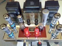
Just wanted 2 show mine...
I was quite astonished by it's sound when a friend of mine gave me the opportunity to rent it for a few days.
Though it was very old (almost 40yrs) it still sounded smooth and quite punchy at the same time.
So i ended up with buying it...
But unfortuntelly did the circuitboard start to fail and after having to stand out with some scratching i just had 2 replace it.
I heard some good things about the MAD-board, so after mailing some with Lloyd Peppard, i deicided to go for it. I got it place and after reassuring 10 times that everything was in place i powered up the ST70... Just 2 find out that the right power transformer had taken it's last breath.
So i bought three new, and started to weld them..
Maybe in a couple of days i could give you some more information about the progress.
Untill then i put in a old picture with the new MAD-board.
Enjoy
Andreas
Attachments
Douglas,
Thank you for your suggested mods - in particular the connection of the diff amp anode loads to the Ultralinear taps. This fits my own schematic preferences/biases for balanced shunt feedback. That is how the "Baby Huey" design came about. I can see that using the Ultralinear taps in this way nicely overcomes the main limitation of that scheme (namely the requirement for a high rp low current tube in the diff amp). The cascode of course will give you the high rp but the low current requirement is entirely negated.
I have a pair of VDV2100 CFB/H Torroidal Output trannies itching for a project. Maybe 3 pairs of KT77 in Mennos "Super Triode" with this front end per monoblock!!!
Thanks again,
Ian
- Status
- This old topic is closed. If you want to reopen this topic, contact a moderator using the "Report Post" button.
- Home
- Amplifiers
- Tubes / Valves
- Dynaco Stereo 70 amplifier