A quick update: Replacing R29 actually brought that channel back to life, but in an unstable state. The fuse blew because it had begun to oscillate at full-power. I discovered this when I tried slowly bringing it up with a variac with an ammeter in series with the negative leg that had blown the fuse. At about 1/3 up the dial, it would begin oscillating at a low frequency. The frequency would rise with the voltage, and the current draw would begin to jump up dramatically.
Facts about the situation based on trying different situations:
-It doesn't oscillate immediately when the ammeter is using the "200ma" inputs. I used this setting first, to set the idle bias, because it's supposed to be in that range. This led me to believe it was OK at first. It will pass a signal, but it isn't stable. With a strong enough signal, it can be set into oscillation.
-It will oscillate immediately at as described above when using the "20A" inputs on the ammeter.
-With no ammeter attached, and just a fuse, it oscillates immediately.
-With the input attached to a preamp, it oscillates.
-With the input left floating open, it oscillates.
-With the input shorted to ground, it does NOT oscillate.
-Replacing the input signal twisted pair wire with high quality shielded wire made no difference. Still oscillates.
-Replacing main filter caps makes no difference. Still oscillates.
Well... contemplating all this has got me thinking... what about these power connections that are going to things that are no longer used on PC-29?... power to the relay circuit, Dynaguard, etc... perhaps this is a probem... since this oscillation is related to some ugly loops somewhere in the rails...
*snip*snip*snip*
oscillation is gone. Music comes out! I will finalize the repairs tomorrow and give a full update to see if this is a solid fix.
Sometimes, the repair is a straight path, and sometimes it is a crooked path. Earlier today, I repaired a LaCimbali M2 superautomatic espresso machine. It was a STRAIGHT path. Easy to go from one point to the next to find the solution.
This amp, has been a CROOKED path, from day 1. For many reasons, not the least of which being the fact that many hands have been in it before mine, doing many "improvements" etc... it's almost a miracle I got it singing again.
This amp, has been a CROOKED path, from day 1. For many reasons, not the least of which being the fact that many hands have been in it before mine, doing many "improvements" etc... it's almost a miracle I got it singing again.
Well, personally with my best speaker pair costing 10X what my most expensive amp cost (the Dynaco ST70, $60 working) and my backup speakers costing 5X, I would try to fix the dynagard or come up with something better. I just spent most of a winter trying to come up with something better than a DC detection crowbar (SCR) that melts the SCR off the transistor PWB instead of tripping the breaker.
I'd certainly jimmy the relay closed or jumper it while I was debugging into a pair of high power resistors, but after that I would try to make the dynagard work.
It is true, wires hanging out in space to high gain points can cause oscillations. Did you have speakers on the output while you were debugging? to detect oscillations and other strange sounds? On each channel I use two 5 ohm 225 W resistors in series and across one resistor have a 4 ohm car radio speaker protected by >2000 uf back to back capacitors in series from DC . After the amp was sort of working the speaker helped me detect several strange sounds. It would pop and go soft when the amp whanged into DC output due to a bad (factory) solder joint on an op amp input. And I also had a radio frequency oscillation caused by a bad solder joint on the base trace of the output transistors. That I had to detect with a VOM on AC scale with a capacitor in series with the input. No sound, big AC voltage out, must be ultrasonic or infrasonic. (DVM's won't see RF, they just go nuts from the interferance). There are lots of ways to mess up.
This amp I am talking about, the repairman before me had totally disabled the B channel, tying off the power feed wires and output wires, and put labels in the B input "don't use ". I realize businesses have to be economic compared to the cost of a new amp, but I learned a lot tracing down the bad factory solder joint, that hadn't been repaired since 1994. My Hammond organ #9574 also had a totally untouched solder joint on the "internal - external" amp switch that had been missed by repairmen into the chassis to replace the nearby tantalum caps in 1969, 1970, and 1974 according to the dates on the caps.
Last edited:
The Dynaguard appears to be a function separate from the protection relay. It looks like a pair of clipping diodes whose turn-on threshold is dynamically controlled by the output signal. Interesting idea, but I don't want it in there. One of the previous persons to fool around inside this amp had already removed the diodes anyway.
Having the protection relay is definitely a good idea, though. I will see about putting in a new circuit for controlling it and a new relay. I don't trust the old one to give reliable service.
I tested it with a pair of very cheap speakers that I don't care about damaging. It was surprising, the oscillation was such that even the variac began vibrating, even when the oscillation coming from the speakers was at a low level.
When I'm testing stuff on the bench, like checking bias and voltages, etc, I have dummy loads made of banks of power resistors.
Last edited:
I can't say anything about the quality of the relays you have, but a good relay is good to have in series with the speaker. Even more useful is a triac or pair of SCR's to short out the speaker on dc detected while waiting for the relay to break the current. Peavey uses a a triac connected between speaker and speaker ground, triggered by a detection circuit. The detection circuit is a diac or SBS like a powerex BD08d or 2N4992 that conducts either way over 8 v. Then behind that is a RC filter, a 47kohm tied to the speaker hot and the bottom to a 2.2 uf bidirectional cap ( I used ceramic as a replacement). The filter point between the SBS, the resistor and the cap ties to the Triac gate. Bottom of the triac goes to speaker ground The bottom of the filter cap goes to speaker ground. You can see this circuit on the CS800x or PV-1.3k schematics on eserviceinfo.com.
The PC30 looks sort of like that with two zeners, but the RC is differently hooked up and the SCR they trigger pull the relay, not shorting out the speaker.
I'm not so convinced the op amp part of the dynagard is as useful. For sure op amps weren't very fast in 1973. I don't understand it, but as a VI limiter it is not probably helpful.
The test speaker blocked by a big cap in parallel with your load resistor is useful for hearing problems,IMHO. Problems like oscillations and DC on the output sound funny. Cool your variac made a noise.
Last edited:
The Dynaguard in the ST400/416 is to limit power during normal usage not so much as protection in the case of amp failure. Both amps still have VI limiters and DC detector/relay for that purpose. Other than the fact the Dynaguard and the DC detector are on the same PCB they are separate circuits. The Dynaguard can be turned off and you will still have the VI limiters and DC protection.
Craig
Craig
Well, this thing is still oscillating. As I slowly bring up the voltage with a variac, at around 21-25v on the rails it will start to oscillate. Starts as a slow "putt-putt-putt" motorboating and goes up in frequency as voltage goes up, and current draw goes up exponentially. Can't say what the upper limits of frequency and current are as its oscillating, because at that point it blows fuses from so much being drawn.
Since it's oscillating at full voltage, it's impossible for me to take any measurements under those conditions. So, I set the rail voltage to about 17v, where it's not yet oscillating, and compared measurements to those on the good channel at the same voltage. The voltages measured were very close to one another - nothing stood out as being way off, with the only exception being the amount of current drawn by the channel at that voltage. In the good channel, it draws about 80mA at 17v. In the bad channel, it was about 40mA at 17v. But this is maybe just a difference in bias adjustment? The bad channel hasn't been adjusted at all yet. The good channel draws 150mA at full voltage (~75v). The original bias and offset trimmers have been replaced with modern multiturn ones. Work excellent - was able to dial offset in the good channel to less than .01mV.
PC-29 and everything associated with it have been completely removed. For all purpose of troubleshooting this, it's safe to say we're looking at a single PC-28 all by itself with nothing else to interact with it.
At this point I'm tempted to say the instability lies in the physical board itself. In its past, the area around R33, R32, R27, R31, and C15 was very badly damaged when these components burned. The board was burned down to the reinforcing fibres and very charred. All those burned components had been replaced already before I even looked at it, but the board wasn't cleaned up very well. I cleaned it with some alcohol to try an get as much of the charring off of it as possible, but it hasn't helped.
What makes it even more frustrating is that there have been a couple moments where it didn't oscillate. I'm at a loss as to where to look at this point. I'm very close to just etching a new board and completely rebuilding it from scratch.
Hi,
One advice to prevent blowing fuses it is the use of a "dim bulb tester". Do a Google on how to built one. It will let you check the amplifier voltages without blowing the fuses. If the board it is chattered that the board look like carbon then you must clean it or remove it because it will become conductive. Specially when you have high voltage. I had one time a problem with a brown Dynaco driver board that was scorched and it was making like a cracking noises. Replaced it and everything started working good again.
One advice to prevent blowing fuses it is the use of a "dim bulb tester". Do a Google on how to built one. It will let you check the amplifier voltages without blowing the fuses. If the board it is chattered that the board look like carbon then you must clean it or remove it because it will become conductive. Specially when you have high voltage. I had one time a problem with a brown Dynaco driver board that was scorched and it was making like a cracking noises. Replaced it and everything started working good again.
Its a matter of going through the amp from the front end looking for wrong voltages.
If I get stuck fixing an amp I remove all semiconductors and test them on a meter.
While they are out I check all discrete components for value.
This method only failed me once when someone had stuck in a PNP instead of an NPN transistor ! Even then I should have checked polarity on my DMM.
Sods law works here so it is bound to be the last transistor you remove that is faulty !
Aye, so much has been replaced in it already... I've had at least half the semiconductors out to test, surely it will end up being the one I hadn't removed yet.
None of the output transistors are original, they've all been replaced with a jumble of different types. I've tested them all, and they're all "good", but maybe an inappropriate choice by whomever replaced them has caused it to be unstable? I'm tempted to pull the ones from the good channel and stick them in the sockets of the bad to see if that makes any difference.
None of the output transistors are original, they've all been replaced with a jumble of different types. I've tested them all, and they're all "good", but maybe an inappropriate choice by whomever replaced them has caused it to be unstable? I'm tempted to pull the ones from the good channel and stick them in the sockets of the bad to see if that makes any difference.
I second the motion. Dynaco boards were paper based (at least on the ST70 and sT120 I've got) and when the components burn, the underlieing paper can make carbon tracks. Carbon tracks and high voltage don't get along. I was able to repair burned away traces on the board in the Peavey PV1.3k I just repaired by patching across with teflon insulated wire, but those were glass reinforced boards. Burnt glass is sand, burnt paper is carbon.Well, this thing is still oscillating.
At this point I'm tempted to say the instability lies in the physical board itself. In its past, the area around R33, R32, R27, R31, and C15 was very badly damaged when these components burned. The board was burned down to the reinforcing fibres and very charred. All those burned components had been replaced already before I even looked at it, but the board wasn't cleaned up very well. I cleaned it with some alcohol to try an get as much of the charring off of it as possible, but it hasn't helped.
I'm very close to just etching a new board and completely rebuilding it from scratch.
If you can't take the time to layout and etch a whole board, maybe you can saw out the bad part and splice in a patch that you wire up point to point. I do most of my projects on Nema LE laminate, that saws nicely with wood or hacksaw and drills pretty easily, too. Glass reinforced FR10 is better, but it is a ***** to drill the holes. I can drill the canvas based LE laminate with a hand crank yankee drill.
Then to prevent future fires on the board, you can put fuses in the base driver lines coming back from the output transistors like I did on the PV1.3k. I used blade type automotive fuses, and drilled little holes in the blades to hook over the solid wires of the lead for effective soldering.
Anyway, good luck. Instead of a light bulb in series with the 120 VAC, I used a 1500 W room heater element from a heater with a bad tip over switch. The nichrome wires would crackle if any of the output transistors shorted or the amp whanged into full +DC on the speaker out. (I had a bad solder joint on both the base drive to output transistor line, my fault, and the input op amp feedback terminal, Peavey's fault.)
Another idea is to replace the bad channel with something like the very conventional ST400 but new. The honey badger sold by diyaudio store strikes me as being very conventional and having a totally new board. It doesn't have to be TO247 output transistor packages, you could run wires over to your TO3's on the heatsink for example.
Oh, another thing. Stressed output transistors can "test okay" at 2 v with the DVM, and break down under real voltage. Mooly said he checks gain of used transistors, I don't have any such instrument. I've been putting 17 VDC (peak of a 12 V car battery charger with filter capacitor) current limited by a 47k resistor, on my transistors collectors, with the base and emitter shorted together. Measure the current with a DVM. If the current of a used transistor is higher than the current from a new transistor, that one is bad. Usually 2 to 3 times the current on the "bad" ones; It is not hard to tell the stressed parts from the new parts. I was able to save 3 of my 20 output transistors and two of the four TO3 driver transistors. Of course, negative voltage on collector for PNP transistors.
Last edited:
Well, I just tried swapping output transistors from the good channel to the bad one. This stopped the oscillation. This is no doubt due to the transistors (NTE60) having half the bandwidth of what was in there (MJ15023). But, the channel still isn't behaving properly. It's drawing about half as much current as it should at idle and adjusting the bias trimmer makes no change. The trimmer itself has just been replaced with a new multiturn one, so I think we can rule out that being the fault.
This board is made from epoxy/glass. I may still end up making a new one even if the burn on the old one isn't the problem. I've made many boards and could probably knock it out in an afternoon.
This board is made from epoxy/glass. I may still end up making a new one even if the burn on the old one isn't the problem. I've made many boards and could probably knock it out in an afternoon.
Still working on this. Got it stable with no oscillation. I'm thinking it was caused by there being a gross mismatch of power transistors. Whoever had worked on it previously had installed a crazy mix of transistors that didn't work well together at all. Now it has all MJ15022/3 and it's stable.
But the problem of it not biasing up is still there. Been measuring voltages and none of them seem off. It just sticks at 70mA no matter how I adjust P2. Voltage at the wiper of P2 stays at 1,1v no matter where it is. I checked it and the resistance is changing as it should when it is adjusted, so it's not a problem with the trimmer. What could be causing this? While adjusting it, it seems that it might jump to another voltage for a second, then settle right back to 1,1v.
Q9 and Q8, both test OK. Not sure where to look next. All the resistors associated with the bias network are OK.
Have both channels idling at 130mA and got the output offset trimmed to less than 1mV. Playing music thru it now and both channels are singing along as they should. Looks like I've got this one fixed!
And I'm hearing zero hum or noise out of the speakers when the music is turned down... I completely rewired the entire power supply and replaced the main filter caps, and it sounds like my star-on-star scheme worked perfect. Thanks, Bob Cordell for educating me about good power supply grounding in your very informative book.")
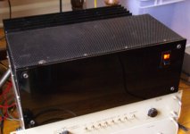
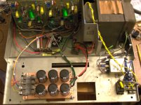
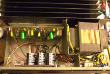
And thanks to everyone who gave advice in this thread. I took it all to heart, and now I have a functioning amp for my friend. I'll post up some photos to show it off. The new power supply and wiring is worth showing off, I think. I feel I made some good improvements over the original layout. The outside looks beautiful too, but that was my friend's doing. My work was all on the inside.
And I'm hearing zero hum or noise out of the speakers when the music is turned down... I completely rewired the entire power supply and replaced the main filter caps, and it sounds like my star-on-star scheme worked perfect. Thanks, Bob Cordell for educating me about good power supply grounding in your very informative book.
And thanks to everyone who gave advice in this thread. I took it all to heart, and now I have a functioning amp for my friend. I'll post up some photos to show it off. The new power supply and wiring is worth showing off, I think. I feel I made some good improvements over the original layout. The outside looks beautiful too, but that was my friend's doing. My work was all on the inside.
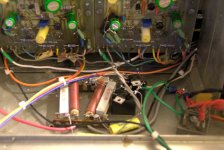
Here are photos of the amp after the repairs. If you've ever seen inside a Stereo 400, you'll be able to see I've rewired nearly the entire thing. It is much easier to access everything for service now. I hand-etched the new cap/fuse board with a Dremel tool. You can see the damage done to the board. I had to air-wire some of the resistors over the top of the board in places where the tracks had been burned off. PC-29 and everything associated with it has been removed. I suppose this makes it more like an ST-410 now.
I was able to get the noise in this amp down to an extremely low level. You can only hear the tiniest hiss if you put your ear right up to the tweeter, and there's no hum in the speakers that I could hear, though there is a little bit of some physical vibration from the transformer. Overall, I'm happy with the results.
I was able to get the noise in this amp down to an extremely low level. You can only hear the tiniest hiss if you put your ear right up to the tweeter, and there's no hum in the speakers that I could hear, though there is a little bit of some physical vibration from the transformer. Overall, I'm happy with the results.
Attachments
I'm popping in here too late to be of any immediate use, but let me add my .02 just for future consideration: When you have a system -- any kind, not just audio amplifiers -- that has/requires feedback, and that system is misbehaving, you will drive yourself insane and waste enormous amounts of time trying to troubleshoot it with those feedback loop(s) closed. In the case of this thing, the first thing you should have done is to lift the feedback resistor that couples output to the inverting input (or connect the output side of it to ground to make sure you have bias current available for the front end). I'd have also disconnected the output devices. Then you have a simple open-loop op-amp type of thing that you can examine step by step by applying suitably small input voltages to the non-inverting input. Sure, it'll saturate one way or the other, but so what? You will adjust the input mv by mv to watch it pass through the linear region, and if it *doesn't*, then you have an easily-isolated place to start looking for a problem. Which, as you probably have discovered, can be one of many. But with a methodical approach, you can isolate them one by one. And if things *still* don't make sense (example -- the voltage amplification stage isn't doing what you expect) you can isolate parts step-by-step until you find the things that aren't working. And you can use other troubleshooting tricks like connecting a milliammeter on a current stage without concern for downstream components.
But above freakin' all, DON'T GUESS!!
And one more piece of advice -- don't completely rely on what a scope appears to tell you. In situations like you had here, especially when apparently some idiot was swapping parts willy-nilly, you can have small parasitic oscillations at GHz frequencies that simply disappear on cheap scopes. Those oscillations can easily lead you down all kinds of garden paths, because they make things look like something they're not.
Anyway, the moral of the story is: Get it working open-loop with plausible and repeatable behavior, THEN re-enable the feedback.
Last edited:
Congratulations. Nice looking job for all the patching you had to do. My Peavey with the white teflon wire bridging the burnt off lands in the PWB is much more obvious. Glad the sound is back to stellar.
I've got NTE60's in my Dynakit ST120. Nice transistor if you have matched pairs. According to the datasheet, probably a white box MJ15003, IMHO.
I've got NTE60's in my Dynakit ST120. Nice transistor if you have matched pairs. According to the datasheet, probably a white box MJ15003, IMHO.
- Status
- This old topic is closed. If you want to reopen this topic, contact a moderator using the "Report Post" button.
- Home
- Amplifiers
- Solid State
- Dynaco Stereo 400 Headache