Well dear friends, uncle Charlie is back again.
The misunderstanding was caused by my mistake.
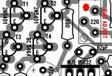
The schematic does not show the correct part really used in the prototype...i have always used MJE15032 transistor for first and second VAS.... my intention was to replace but i have not another transistor for that position...soon i will have, as Evette from Canadá is sending me hundreds.
Old pictures posted in this thread may show you the second VAS big heatsink and you may see the MJE15032 in the first VAS position.
This was the trouble.... the prototype was using MJE15032 and i made the first mistake, posting a schematic from my simulator (generated by simulator and converted in pdf) showing the BC840.... this unit was just to make tries to see if i could find a transistor that could help me to reduce THD in the simulator analisis....i knew it could not face the voltage....was a try only and by a mistake it was shown in the schematic diagram.....gladly no one have built.... that transistor would not work there..it is a low voltage unit.
Then i made another mistake.... i have replaced after someone pointed the error,by another wrong one... the 2N5551 also cannot do the job...it can face the voltage but not the power.
Another mistake in the schematic, the first VAS emitter resistance is not 50 ohms.... it is 560 ohms....this is what was designed and assembled in the working prototype...almost 500 miliwatts iddle is the power in that transistor..without signal.
So, as people have not the prototype, or an assembled circuit, only watching the schematic, found these errors and complained...... and me....by my side, having a working prototype, could not accept the amplifier was not working..that would explode or be damage.... was working.... and working for monthes long.
Some small adjustments are being made...first to make the schematic a good copy of the reality..also some small tuning will be made...i do not like the 25 kilohertz square wave...i think we can make it better....also the limiter adjustment resistances will have a trimpot to adjust clipping simetrically.
We still have a "more real" schematic,but will have small modifications..so..i is provisory only.
I have made tests with 3.5 ohms load...inductive+resistive load..and the amplifier survived, using only 5 pairs (this is the way prototype is) in the ouput... and because the supply i have used dropped the voltage to more or less 70V.
I believe it will work fine with reactive loads when using the 10 output pairs suggested...and soon i will test that...sadly will not be able to test with 3.5 ohms because my supply voltage drop.... as i will not have 80 volts..but i will be able to test with 8 ohms.
As i could not test to lower impedances.... and because of that i cannot guarantee the amplifier survival under these circunstances..under these conditions, them i would like to say the amplifier can work with 8 and 4 ohms only.
I have made some videos.... not only explaining these things, the main differences between the schematic and real life prototype, and some testings made.... i hope you enjoy.
Sorry by the bad image...i have two cameras..one has good video and other has good audio...i have not digital camera that has good audio and video.
Troyan amplifier is not guaranteed to work with speakers, or output impedances, lower than 4 ohms
Next post will have links to videos.
The misunderstanding was caused by my mistake.
The schematic does not show the correct part really used in the prototype...i have always used MJE15032 transistor for first and second VAS.... my intention was to replace but i have not another transistor for that position...soon i will have, as Evette from Canadá is sending me hundreds.
Old pictures posted in this thread may show you the second VAS big heatsink and you may see the MJE15032 in the first VAS position.
This was the trouble.... the prototype was using MJE15032 and i made the first mistake, posting a schematic from my simulator (generated by simulator and converted in pdf) showing the BC840.... this unit was just to make tries to see if i could find a transistor that could help me to reduce THD in the simulator analisis....i knew it could not face the voltage....was a try only and by a mistake it was shown in the schematic diagram.....gladly no one have built.... that transistor would not work there..it is a low voltage unit.
Then i made another mistake.... i have replaced after someone pointed the error,by another wrong one... the 2N5551 also cannot do the job...it can face the voltage but not the power.
Another mistake in the schematic, the first VAS emitter resistance is not 50 ohms.... it is 560 ohms....this is what was designed and assembled in the working prototype...almost 500 miliwatts iddle is the power in that transistor..without signal.
So, as people have not the prototype, or an assembled circuit, only watching the schematic, found these errors and complained...... and me....by my side, having a working prototype, could not accept the amplifier was not working..that would explode or be damage.... was working.... and working for monthes long.
Some small adjustments are being made...first to make the schematic a good copy of the reality..also some small tuning will be made...i do not like the 25 kilohertz square wave...i think we can make it better....also the limiter adjustment resistances will have a trimpot to adjust clipping simetrically.
We still have a "more real" schematic,but will have small modifications..so..i is provisory only.
I have made tests with 3.5 ohms load...inductive+resistive load..and the amplifier survived, using only 5 pairs (this is the way prototype is) in the ouput... and because the supply i have used dropped the voltage to more or less 70V.
I believe it will work fine with reactive loads when using the 10 output pairs suggested...and soon i will test that...sadly will not be able to test with 3.5 ohms because my supply voltage drop.... as i will not have 80 volts..but i will be able to test with 8 ohms.
As i could not test to lower impedances.... and because of that i cannot guarantee the amplifier survival under these circunstances..under these conditions, them i would like to say the amplifier can work with 8 and 4 ohms only.
I have made some videos.... not only explaining these things, the main differences between the schematic and real life prototype, and some testings made.... i hope you enjoy.
Sorry by the bad image...i have two cameras..one has good video and other has good audio...i have not digital camera that has good audio and video.
Troyan amplifier is not guaranteed to work with speakers, or output impedances, lower than 4 ohms
Next post will have links to videos.
Last edited:

Here some videos about Troyan tests.
First video explain all that misunderstanding we had..... differences from real life amplifier and the prototype:
Sorry about video quality:
YouTube - Introduction - Troyan - errors being fixed in diagram
YouTube - 1 - Troyan test, set up presentation.
YouTube - 2 - Troyan test, stand by supply voltage
YouTube - 3 - Troyan supply voltage drop - 80 to 70V
YouTube - 4 - Troyan output, 37.5V RMS over 3.5 ohms
YouTube - 5 - Troyan test, conclusion
Enjoy!
regards,
Carlos
This is the updated schematic and layout from Troyan amplifier
Thank you Alex mm by your help.
I intend to open a new thread.... builder's thread...for builders only, this way we gonna have only the needed informations.
This amplifier schematic, layout and so on will go to Greg Erskine pages too..but i want to refine it first...also i have not part's list and Greg will ask me the BOM..also adjustment instructions and other details.
In advance i want to check how much interest people have to build big amplifiers...this one may reach 650 watts each channel, unclipped, 4 ohms loads, with 80 plus 80 volts supply (huge one or SMPS one) and THD will be around 0.021% to 4 ohms.... and of course smaller to 8 ohms.
Building a stereo, then having two channels added.... 650W plus 650W will result in 1300 Watts total.... a strong amplifier.
Well..this is simulator specifications only..... to see some real thing you should watch the videos made.....with reality problems...supply with voltage drop.... poor builder that has only 10.000uf plus 10.000uf by 100 volts condensers..and so on...hehehehe...it is hard to obtain full power this way")
We will go progressing stimulated by the interest...having huge interest the amplifier will be re-tuned for maximum performance (sonic)...and charts, informations and videos will be produced and published.
Let's see if there's something more to be fixed...i will inspect the prototype in details to check the schematic....to be sure they are the same.
regards,
Carlos
Thank you Alex mm by your help.
I intend to open a new thread.... builder's thread...for builders only, this way we gonna have only the needed informations.
This amplifier schematic, layout and so on will go to Greg Erskine pages too..but i want to refine it first...also i have not part's list and Greg will ask me the BOM..also adjustment instructions and other details.
In advance i want to check how much interest people have to build big amplifiers...this one may reach 650 watts each channel, unclipped, 4 ohms loads, with 80 plus 80 volts supply (huge one or SMPS one) and THD will be around 0.021% to 4 ohms.... and of course smaller to 8 ohms.
Building a stereo, then having two channels added.... 650W plus 650W will result in 1300 Watts total.... a strong amplifier.
Well..this is simulator specifications only..... to see some real thing you should watch the videos made.....with reality problems...supply with voltage drop.... poor builder that has only 10.000uf plus 10.000uf by 100 volts condensers..and so on...hehehehe...it is hard to obtain full power this way
We will go progressing stimulated by the interest...having huge interest the amplifier will be re-tuned for maximum performance (sonic)...and charts, informations and videos will be produced and published.
Let's see if there's something more to be fixed...i will inspect the prototype in details to check the schematic....to be sure they are the same.
regards,
Carlos
Attachments
Alex mm, Dx Corporation European Layout Laboratories
have made nice X Ray vision...but too much big.
Then i have splitted in two parts to show you... soon i will learn how to manipulat layers and will have images by myself.
This board made by Alexandru, looks alike the Enterprise Space Ship.... wonderfull..not nice!..just wonderfull!
Builders!....please, write me and i will upload to your email adress the full size pdf file:
Use direct email....forum PM cannot attach images, goto:
carlos.eugenio1951@yahoo.com
regards,
Carlos
Attachments
Last edited:
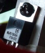
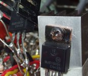
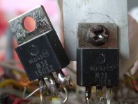
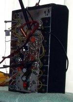
These pictures shows you the VAS stages...the way it was since the first day
the Troyan was built, and that was there working till yesterday when i have removed them and substituted by MJE15034 (from Evette - Canadá).
I had colector lead broken in the transistor case..could not solder anymore... this is the main reason i use to cut leads short..this is to avoid "mechanicall advantage"..... Alavanca (lever) in my language, to avoid broke the lead in a easy way.
regards,
Carlos
Attachments
Gladly i am receiving people in my direct email adress
People that intend to build the amplifier...this Troyan.
I feel happy, of course, i am human..... i have feelings...all the good and bad feeling we all have.... but, i have to inform things about:
- The amplifier was tested....passed!....but the board was not tested!
- The amplifier is an average performer...alike hundreds of others you can find..it have anything special in sonics....a very good sound.... a very good performance, high fidelity,but not awsome..just good and fair....does not have superior sound alike Blameless or Dx Blame ST...it is a power plant.
Also, despite i have tested real life, some good engineers had worries about the amplifier..some of them said would explode, damage, cause harm results...some of them asked moderators to close the thread, to vaporize the design and desintegrate the whole thing...so...the amplifier is under suspectious in the Academic group.
I felt reliable, worked for hundreds hours...and i cannot understand (really) their worries..maybe some mistakes i have made in the schematics.
I am a self made man..that learned in this same forum... someone that have practice and not too much theories..i have made dozen courses, long studies in Brazil and in outside Brazil...but i have not the degree..so...not too much addicted to calculations... i have perceived we have to adjust things to real life and i felt good to be in the "production line" instead of the design department...i am creating in the workbench...burning fingers...if i have doubts will burn, will explode, then i submit to test, to torture, to see if will happens or not.
The one made the layout is a friend, a cooperator in the Big Corporation of high quality amplifiers, the Dx Corporation, the Audio amplifiers Union.... we are a virtual group of builders... associated inside the virtual corporation of freak fanatics..... Alexandru is not my employee...he belongs to the virtual Corp. that has not a boss, has a representative chaiman wich is "Uncle Charlie".
Alexandru made the board...the layout..he has the gerber files or can have them..it is up to him publish or not the gerber files...i really do not mind he publish or not....i want him free and happy to do whatever he wants to do..he is a cooperator, not my employee.
The man, Alexandru, or Alexmm, is very good, he have never made a mistake..all his boards had no revision because of him...revisions where made because uncle charlie making foolishes.... i think his board is fine...but, Alex is human..he can make mistakes alike all humans does.
So..you will be board layout beta testers..... it think Alex have not build and i am not sure if he intend to do that...i think not..he have not all that free time...so..i cannot guarantee if we may have a copper line missed or not in that board.
Build this layout under your own risk..i can guarantee the circuit, but i cannot do the same for this board..untested!
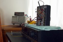
Pictures shows a 250 watts heatsink, used in a Television transmitter, the one had 250 watts consumption continuously.... this heatsink is too much small to one channel, at least two of them should be used, and each one of them with their own fan blower operating with 8 volts DC not to produce too much noise.... this one overheated to almost 80 degrées celsius while i had an enormous fan blowing air to it...as a 60 centimeters diameter high powered fan...this one is too much small!
regards,
Carlos
People that intend to build the amplifier...this Troyan.
I feel happy, of course, i am human..... i have feelings...all the good and bad feeling we all have.... but, i have to inform things about:
- The amplifier was tested....passed!....but the board was not tested!
- The amplifier is an average performer...alike hundreds of others you can find..it have anything special in sonics....a very good sound.... a very good performance, high fidelity,but not awsome..just good and fair....does not have superior sound alike Blameless or Dx Blame ST...it is a power plant.
Also, despite i have tested real life, some good engineers had worries about the amplifier..some of them said would explode, damage, cause harm results...some of them asked moderators to close the thread, to vaporize the design and desintegrate the whole thing...so...the amplifier is under suspectious in the Academic group.
I felt reliable, worked for hundreds hours...and i cannot understand (really) their worries..maybe some mistakes i have made in the schematics.
I am a self made man..that learned in this same forum... someone that have practice and not too much theories..i have made dozen courses, long studies in Brazil and in outside Brazil...but i have not the degree..so...not too much addicted to calculations... i have perceived we have to adjust things to real life and i felt good to be in the "production line" instead of the design department...i am creating in the workbench...burning fingers...if i have doubts will burn, will explode, then i submit to test, to torture, to see if will happens or not.
The one made the layout is a friend, a cooperator in the Big Corporation of high quality amplifiers, the Dx Corporation, the Audio amplifiers Union.... we are a virtual group of builders... associated inside the virtual corporation of freak fanatics..... Alexandru is not my employee...he belongs to the virtual Corp. that has not a boss, has a representative chaiman wich is "Uncle Charlie".
Alexandru made the board...the layout..he has the gerber files or can have them..it is up to him publish or not the gerber files...i really do not mind he publish or not....i want him free and happy to do whatever he wants to do..he is a cooperator, not my employee.
The man, Alexandru, or Alexmm, is very good, he have never made a mistake..all his boards had no revision because of him...revisions where made because uncle charlie making foolishes.... i think his board is fine...but, Alex is human..he can make mistakes alike all humans does.
So..you will be board layout beta testers..... it think Alex have not build and i am not sure if he intend to do that...i think not..he have not all that free time...so..i cannot guarantee if we may have a copper line missed or not in that board.
Build this layout under your own risk..i can guarantee the circuit, but i cannot do the same for this board..untested!
Pictures shows a 250 watts heatsink, used in a Television transmitter, the one had 250 watts consumption continuously.... this heatsink is too much small to one channel, at least two of them should be used, and each one of them with their own fan blower operating with 8 volts DC not to produce too much noise.... this one overheated to almost 80 degrées celsius while i had an enormous fan blowing air to it...as a 60 centimeters diameter high powered fan...this one is too much small!
regards,
Carlos
Attachments
Last edited:
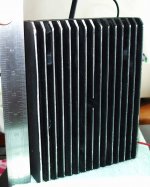
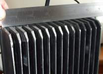
The heatsink i suggest to each channel should be big as this one
Then you will be able to use full power without troubles...but use a low speed fan blower (8 volts supply, an LM7808 may help to reduce from 12 to 16V)
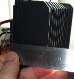
2 of these ones to each channel..one for NPN and other for PNP...or equivalent to this area exposed to the air..do not worry about thickness, it just produce a delay in the heat transference..the heat exchange is made by area exposed to the air.
The images have dimensions in the place of identification names.
This one proved as not good enougth using only one to a single channel...so, i think 2 units, using fan blower may be good..or the equivalent in size..i am not absolutelly sure...but i can sniff that because of long time practice and i really think it will fit.
I will study, once again, fuses values and supply condenser values..will inform you as soon as i see several folks interested.
regards,
Carlos
Then you will be able to use full power without troubles...but use a low speed fan blower (8 volts supply, an LM7808 may help to reduce from 12 to 16V)
2 of these ones to each channel..one for NPN and other for PNP...or equivalent to this area exposed to the air..do not worry about thickness, it just produce a delay in the heat transference..the heat exchange is made by area exposed to the air.
The images have dimensions in the place of identification names.
This one proved as not good enougth using only one to a single channel...so, i think 2 units, using fan blower may be good..or the equivalent in size..i am not absolutelly sure...but i can sniff that because of long time practice and i really think it will fit.
I will study, once again, fuses values and supply condenser values..will inform you as soon as i see several folks interested.
regards,
Carlos
Attachments
The protection act only by limiting the current to 1.5 A per power
device whatever the output voltage.
R30/31 resistors are useless since they are not correctly
settled for the circuit to provide a I/V protection...
The VAS is not protected if ever the output stage
limiting current circuit start to conduct...
device whatever the output voltage.
R30/31 resistors are useless since they are not correctly
settled for the circuit to provide a I/V protection...
The VAS is not protected if ever the output stage
limiting current circuit start to conduct...
Thank you dear Wahab...also you have supported me in the
"vilifying chapter"..and this made me feel you are fair.
This amplifier, alike many others, have a lot of room to evolute...maybe we gonna have evolution 1 and evolution 2... as soon we find troubles in the prototype, fuses burning or some problem not perceived till this moment.
The V/I limiter will be better adjusted soon, and the builders will be informed by direct mail and also in this forum thread too..of course.
The protector in the VAS will be use if tests shows it can be destroyed while using other loads then normal speakers...or... some hard to face loads i will produce..some torture equivalent loads... wanna help publishing some hard loads?...post it here to everybody , please.
I am reading and will be reading your posts with attention dear Wahab... and maybe i will use some of your instructions, because you proved to be good in the 220 ohms Dx Blame ST chapter.... i tried several values, and the optimum value was the one you have calculated in advance than i did it.
I will modify if i perceive that in real life i have some danger...all these protections use to kill the sound, to compress, or to limit swing...so, i have the right not to appreciate them and to avoid to use them.
Protections are being used in Integrated Circuits because their case size...or they use or the small chip will melt...it is not our case..observe we use a lot of power transistors, power VAS, power drivers, big heatsinks...it is another approach, a more purist approach then a protective approach...Dx Corporation wants safe and reliable amplifiers..but not so protected in a such way can harm sonics.....sound reproduction, the performance matters...my ampliifier are not final work to present in academic foruns...not to show in the College to obtain post graduation or graduation.... these amplifiers are made to reproduce nice music without smoke.... even if they are not fine as an acadhemic work to present for University teachers..... i do not need that...my advantage...no one can criticise a non engineer producing some small differences compared to the perfection...you should not worry about dear Wahab...your name is not in this amplifier, not your responsability to prove your capacity...if this is not perfect will not send shame on you...also will not send shame on me....as i am not an engineer...i can produce non perfect things..common sense will forgive me.... it is different for you, i understand that..you will lose your academic degree if you publish not perfect designs.
Well.... some chips are so perfectly designed that sounds bad..because the protections, they are rated to 100watts and cannot work with that power because the case...so..they can give you 40watts continuously.... but this is triggering the protections, and the sound is not good anymore (I have tested several)..they are good for 10watts only... exactly in the range of power no protection enters in operation...so...you see the difference of my style of design (practice design) and the academic design..and you gonna perceive it in the sound reproduction too...i have enormous advantage Wahab.... i can make some small mistakes in the name of sonics.....you cannot...sorry about that...very sad this stuff...the world became slave to technocracism and this results,sometimes, a loss in performance to humans...and great performance for instruments.
My amplifiers were made by a human (uncle charlie) and made for humans to listen....i really do not care about instruments.... for an accident, this one measure reasonable, even i had not worried about that while making it.
About circuit survival or not survival, as you could read the text published by Chief Moderator Salas, is something to be adjusted between me and my builders..and for sure i will take care of them, to avoid them to have terrible surprises.
By the way, dear Wahab, the amplifier is playing now, here at my side...loud music..nice music with nice sonics...working..if not perfectly, at least playing good sound without smoke.
You see, here you have a big post...and about theories..something i do not appreciate ..but i have made the big text in respect the good engineer you are (and have supported and protected me when i had the need)...but for sure will not spend so many time once again...as i really thing the conversation is not too much productive.... you will continue with your way of thinking because you cannot do different..you have to defend your certificate talking about precision..and i will be continuing searching for sonics without bother with design perfection.
It is alike two guys that lives as neighboors...one plant vegetables...other has water tanks and he produce fishes.....one prays for God asking for rain, he needs rain for his plants... the other one pray for God asking not to rain..the rain changes the watter temperature and PH (acid or basic) and this is no good for fishes to survive, in special the young ones.... these guys are living in the opposite extremes of a rope (the game to push the rope..one team each rope extreme)... different interests..they are different and will never agreed about rain...we will never agreed about audio amplifiers.
Understand me and try to be superior to the words....capture the meaning only..... we are in a DIY forum...means to do by yourself.... nowhere we read that this is an enginner forum, to protect and develop perfect engineering practices... this place we have is more a finger burn place then a place to have circuit analisis.... degree of harm in one equipment.... performance analisis...designer quality judgement and so on.... some guys try all the time to deviate the forum main proposal.... and DIY have not the demand to be an enginner or an audio scientist...maybe means someone that copy schematic and produce...or others that try to create by themselves.... the Academic group landed in this forum and use to try to deviate the north to high level electronics..or the development of audio electronics...this is not the objective here....i am on topic to the forum (DIY)...about others...think about that.
regards,
Carlos
Last edited:
The Troyan was made by a male.... the ones likes girls above all and everything...
the ones girls like....the amplifier wasmade to be strong and not to be kind with speaker..to give them a hard time..to punch with strength... to kick them without mercy.
Was made this ugly macho way to work, this is just a working prototype.... i had not the concern to make it nice...i had not spent a second with worries to make it pretty.
But you have Alexmm beautifull boards if you like them other way...Alex board layout looks alike the "Enterprise space ship"...long and beautifull.
Male does not use makeup...also let the beard grown..also hairs..usually they do not shave ..the voice has low tones ...and so this amplifier is...the beard was there, keept to scratch speaker girls and to say:
- "Me Tarzan...you Jane!
No intention to be kind with anyone of them (speakers in this case)
here is the picture..the rude and monstruous male Amplifier!
Are you a real male?...then build one!
regards,
Carlos
Attachments
Last edited:
Fokker is the Troyan's little brother....the young a little and small brother
Was not approved...too much kind with speaker..... the Troyan is the same Fokker with steróids.
Here a sample...has good speaker in your computer?...big macho speakers?...do you have 100 watts each channel?.... then equalize the whole thing to the loudness human contour.... turn your volume control all the way up!.... increase your computer audio board levels all the way up....wait the Youtube video to load...increase Youtube volume bar to the maximum...
And feel the punch in your body!
YouTube - Audio Amplifier Fokker, by Dx.
regards,
Carlos
The monster!..this time recorded with digital camera
well..not a very good sound...camera does not register low tones..also the tiny speaker had received 40 watts...twenty to each one of them..the power amplifier in less than 10 percent it's maximum...what distorts is the speakers and the camera recording.
other recording uses stereo high quality electret condenser microphone..this is digital camera noisy trash recording.
Feel the emotion!
YouTube - Distorts because powerfull!... the Troyan monster
regards,
Carlos
Alexandru found a small mistake and fixed.
I will be checking resistance wattages very soon...in my unit all resistances are 1/4 watt (prototype)...of course not the power emitter resistances, but the other ones are 1/4 watt.
But it is possible i'm having one of more hot...and this may be fixed soon.
Forum's maximum size allowable to attach images is also informed down the pictures.
regards,
Carlos
Attachments
Last edited:
The PCBoard fixed is too much big to forum maximum size
reason why i have posted in three parts...soon i will manage to operate a viewer, then i will be able to fix these things.
For a while, dear Alex, you could send me smaller files...maximum 190 kilobytes for pdf files.
If a builder wants the big file, then write to my personal email adress and i will provide you:
carlos.eugenio1951@yahoo.com
regards,
Carlos
Attachments
Here you have voltage chart and also some informations about current
Images shows details about symetrical clipping adjustment that will be included in the schematic (fixed) and a resistance to reduce off set that will be included in the schematic as optional.
Much more than other amplifiers, this one drains a huge current and will have external series protective resistances to allow you to measure the stand by current.... these resistances are a little bit big... reason why i will not include them, this time, below the circuit board... the resistance selected will be 100 ohms, as this will limit the current (under short) to something around 0.8A amperes...this resistance power should be a 64 watts resistance to sustain that short for long time....this is too much big..so we gonna use 100 ohms and 10 watts only... to test the amplifier very fast.....
Observe that having a correct assembled amplifier and following the instructions to adjust and trimpot preset value that will be informed, then you will have only 100 miliamperes crossing the 100 ohms resistance and this means the correct current will be 100 miliamperes, and this will have the reading of 10 volts and the power dissipated will be 1 watt only... so... 10 watts to the power you suppose you will dissipate under normal conditions is more than good....also will sustain shorts in the board (mistakes) for some time.
Keeping the 100 ohms we go to some kind of standard...easy of mind calculations without the need the aid of portable calculator machines.
So, because of high power over that series resistances, i will publish resistances measured from positive to ground and negative to ground, allowing you to check your amplifier before powering it on... and also trimpot suggested preset value.
Of course other resistance values can be used..some other values can be even better and cheaper....and you can select the ones you want...i am just keeping some tradition, where Dx amplifiers (alike great Aksa machines) uses 100 ohms series resistance.... a standard of tradition.
regards,
Carlos
Attachments
Here you have voltages you may use to check your amplifier
These voltages are measured to ground....say.... fix your black multimeter probe tip at ground, and measure DC voltages with the red probe tip.
Some voltages depends on the supply voltage...and have value while using 80V supplies...but you may accept plus and minus 20 percent errors without worries.
regards,
Carlos
Attachments
- Status
- Not open for further replies.
- Home
- Amplifiers
- Solid State
- Dx Troyan, a 650 watts channel amplifier.