Precision II could be called the "earthquaker"
It produces so huge sound, in special bass sound,.... the speaker goes moving into my home.... and it is heavy and use rubber feet.
The speaker diafragm almost jumped out from the frame.
It is stronger..... an animal!...stupid force!
What causes that, not only other modifications, but in special Constant Current Sources into the drivers transistors..they never switch off..works hot and send all the output need.
Precision II schematic will not be provide..i think to make sells with this one into the future.
Because i have never listened something so good this way.
25 kilograms speaker is moving a inch each second because the bass...booom...booom...booom...windows will need to be fixed soon...booom!...boom!...and not only boom boom!... i feel afraid the treble will broke my Crystal glasses.
Hugh made the Lifeforce... i have made the Stupidforce... it is 200 watts...but no chance for 200 watts speakers..they will burn and very fast..guaranteed to smoke your speakers...have to use bigger one and place fuses...it is an aberration, an animal of power...my God!
If you want to make something alike, search for Electrocompaniet CCS to drivers, but mine is better made than they made, more expensive mine circuit, and there are a lot of modifications and differences from last Precision and Electrocompaniet circuits.
This one only to Nordic eyes and mine own eyes...sorry.
regards,
Carlos
No, you da man!!!!!!!!!
Uncle Charly, back on topic... is there a way we can increase the input impendance of the amp without loosing all the gains we made and possibly adding a bit of Johnson noise?
The reason is, I'd like to try the lightspeed attenuator this year, and it will not work driving loads as low as the input on the HRII, it may still work with the original DX... or as someone called it, the DX Classic.
yes,Nordic said:is there a way we can increase the input impendance of the amp without loosing all the gains we made and possibly adding a bit of Johnson noise?
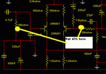
just change the input and NFB resistors and alter the matching caps to maintain the same turn over frequencies.
Finally, check that the mods have not affected stability.
Edit,
DX's pic shows it.
the 4.7uF and the 39k on the input and the 220uF with it's series 1k6 and the other 39k all need to be changed in proportion. The 27pF may need to be experimented with to bring back the stability margins.
Re: Ahahahha...i was faster.... using shorts than you using kilt
what's the on topic point you are trying/failing to make?destroyer X said:
hehe
regards,
Carlos
Re: Todd Johnson (TAJ) made the kindness to prepare a nice
I noticed a mistake in the latest schematic. The complementary device to 2SC4793 should be 2SA1837, not 2SA1819. I'll update it when I get a few minutes.
..Todd
destroyer X said:
schematic for us.
here it is:
regards,
Carlos
I noticed a mistake in the latest schematic. The complementary device to 2SC4793 should be 2SA1837, not 2SA1819. I'll update it when I get a few minutes.
..Todd
They are installed, mainly, to protect the amplifier against polarity invertions.
Because if you invert the polarity, as a human natural mistake, diodes will conduct, will produce a short that will drain huge current.... that current will burn the series fuse you have into the supply.
The diode, despite 1 ampere unit, use to hold 20 times more for a small time...the time needed to melt a fuse...also...if the one burns, you will not loose too much money, because they are very cheap.... and the unit can die in peace if will protect the entire amplifier against worst problems.
The fuse must be installed distant from the board...if burned, it will not burn the fiber glass board...so.... distance is needed.
I think diode protection is a DIY need...from now on...at least mine units will have them.
I can remember a friend that had a very expensive Class D amplifier burned because the board had not those diodes....so...lost 300 times more money....lost all the board..when could have lost a very cheap diode and a fuse...and more usual to happens is to have only the fuse burned.
Now a days, it is very fashion to install huge condensers into the board...can you imagine the explosion of those units if someone invert...and...at same time a second error.... a bigger fuse than the specifications...result is a very loud booom!
regards,
Carlos
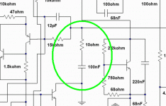
Sorry Todd...the 10K ohms resistance is the trimpot into the Differential
The VBE multiplier transistor has a resistance from base to emitter...it is a variable resistance unit, a trimpot... 1K is the value and adjusted to 820 ohms as a good starting resistance value.
Zobel is here, drawn more to the left as Nordic said.
The ouput coil is not needed...people is removing those coils now a days...but they are needed if the amplifier user connect long cable to the speaker.
The Dx Standard had not output coil, The HRII has output coil and the Precision do not have output coil.... was not needed.
Into the HRII i had to use, to correct a small over shot i had into the square wave... just for the guys loves to watch waveforms....this made waveform more pretty, and also made the corrections into the waveshape i have told you.
Todd... dear friend... this was already explained...take some time.... 10 minutes a day and read the thread (only the Dx thread i am asking you..i have readed the whole forum 3 times!!!).... about zobel, the need or not needed, reasons of it..the coil...all those things was already explored, discussed and explained.
Or ask me directly by mail, because i will be repeating myself, and the ones have readed the thread knows i have posted, many times, comments about those things.... so...for them...the big majority,... i will be repeating and repeating the same old story once again...they may feel tired to read this stuff once more.
Go directly...you have my mail and you are specially welcome.
panzertoo@yahoo.com
regards,
Carlos
Attachments
- Status
- This old topic is closed. If you want to reopen this topic, contact a moderator using the "Report Post" button.
- Home
- Amplifiers
- Solid State
- Dx Precision, finally released... now debugged and better than HRII


