
Hi!
My transformer gives me 35-0-35V AV and that is +-50V rectified. If I change the output transistors to, for example, MJL21193/4 and the drivers to MJE15034, can I use this transformer?
Thank you!
Best options:
1. Buy a new transformer
2. Build a different amp
Best options:
1. Buy a new transformer
2. Build a different amp
I think I'll go for option 2. But only for now... I'll be back for building Dx blame ST latter.
")
Thank you,
Man!..... you do not know how complicated is this question to me to answer
Greg was simple, was direct, was short and was precise.
He has an analitic mind...much better than mine...he was a hell precise.
I am not that way..... sadly i have to say.
Let's go to the long travel...the long run.....you can and also you cannot.
Depends your transformer power...if you substitute drivers for units that can face more power, even this way you keep the weak point to the VAS transistors (Voltage Amplifier Stage) Q6 and Q7 may be destroyed...and this depends your supply.
How dependable this is?
Supplies use to show voltage drop when you suck current...this is normal...but some supplies (weak ones) have more voltage drop....so...your supply can have the voltage reduced to 42 volts when both amplifiers will be pumping full power output...and this is good in your case..... say....bad 50 Volts DC transformers are best than good 50 volts DC transformers...because the first one will maintain the voltage and this may exceed some transistors maximum voltage ratio (dinamically..more than 80 volts peak to peak) when the bad transformers will not exceed...so....depending the sittuation, the bad is the good and the good is the bad..got that?
I have not tested these transistors...they are not in the schematics as you know, also everybody have assembled with the suggested transistors..they have not tried to submit the entire project to a transformer...in other words..the project needing to adapt your transformer..when your transformer should be selected, found, ordered, made, to be adapted to the project.
You may need to increase the output using one more pair... each one of these transistors having it's own base resistance and it's own emitter resistance.
Also you may need to substituted several condensers, to 50 volts or higher voltage.
The input transistors should be substituted by higher voltage units too...so.... another amplifier is what you gonna be making.
This was commented and studied, earlier, several times, in the Dx amplifier thread, the one people do not want to read it entirelly, but it is huge because has all these informations posted, and in details and several times.... in that thread you have hundreds of "social" posts, simple conversation, little chats, some theories, some discussions, some invasions, some divertion, some people asking customized amplifiers, some sub models, some small figths too...and if you filter, saying to yourself, this is to read..this one not...the thread will be 50 percent smaller...i suggest everybody to read...as there i made efforts to post all the tips and trick i have learned in this same forum and during 50 years of audio research building thousands amplifiers.
I have made an amplifier with 55 volts plus and 55 volts minus...because i new the supply was not good.... and this is very good! to use with designs made to lower voltage..as the voltage will drop under dinamic condition and will protect the amplifier...it worked..and continue to work..and transistors are BD139 and BD140......
But i cannot suggest this to you...this have risk...i took the risk to myself.
Your guaranteed of reliability will be void if you change the circuit....not suggested, not appointed, not a good idea....but may work very well...i have not tested to say yes or not....i prefere not to stimulate you to do that.
Here you have the amplifier working (for monthes, at my side..here at my computer room)
YouTube - Using BD139 - supply is 55V
YouTube - 55V, using BD139, PC power of pulse
YouTube - PC power on - pulse going to amplifier
The pulse was not from the amplifier..the amplifier does not have power on noises...this was created..forced..switching my computer on and off....here you see that there's no "power on" noise...you listen only the flip of the switch.
YouTube - Dx Blame ST, none power on thump!
I am proving it can put full power output without burn BD139 here:
YouTube - Dx Blame ST full power
The ugly speaker, surrounded by a circular piece of wood (never painted) is a 4 ohms unit.
So..not an easy question..answer is YES and NO!
regards,
Carlos
Last edited:
You see Greg... Paulo was not decided wich one to build
This happens a lot..when people search for customized things they are really trying to say:
- " I have this transformer and these transistors...if your damn amplifier cannot work with it then i will not build yours ".... so.. they transfer the decision to you to continue undecided.
Statistically speaking..only 5 percent of the ones have asked or intended to use other voltages have assembled.... when people wants to submit the amplifier to their own parts, seems they do not want the amplifier.
Ahahahahahahha!
In this moment, Paulo may be thinking in the Symassym... i am afraid, in the future, he will be building the Dx Blame..... good..build both....i suggest the first model made for Symassym...not the last one posted there.... First and second models are for 35 volts.
Because of that, i really think, dear Greg..you are more prepared than me to conduct threads..you sense things faster, do not spent or waste your time and decide in 2 sentences.
Build another amplifier
Build another transformer.
Congratulations by your superiority Greg.. a beautifull analitic brain you have.....i am ashamed of myself.
regards,
Carlos
This happens a lot..when people search for customized things they are really trying to say:- " I have this transformer and these transistors...if your damn amplifier cannot work with it then i will not build yours ".... so.. they transfer the decision to you to continue undecided.
Statistically speaking..only 5 percent of the ones have asked or intended to use other voltages have assembled.... when people wants to submit the amplifier to their own parts, seems they do not want the amplifier.
Ahahahahahahha!
In this moment, Paulo may be thinking in the Symassym... i am afraid, in the future, he will be building the Dx Blame..... good..build both....i suggest the first model made for Symassym...not the last one posted there.... First and second models are for 35 volts.Because of that, i really think, dear Greg..you are more prepared than me to conduct threads..you sense things faster, do not spent or waste your time and decide in 2 sentences.
Build another amplifier
Build another transformer.
Congratulations by your superiority Greg.. a beautifull analitic brain you have.....i am ashamed of myself.regards,
Carlos
Last edited:
Because of that, i really think, dear Greg..you are more prepared than me to conduct threads..you sense things faster, do not spent or waste your time and decide in 2 sentences.
Build another amplifier
Build another transformer.
I don't think so.
Well...it is better for the Corporation this way
If you had conscience about how good you are..you would kick my .... and take care of your own business..and gonna do it better...i will be very weak abandoned by you.
So.... please..keep this way...do not think so.
regards,
Carlos
If you had conscience about how good you are..you would kick my .... and take care of your own business..and gonna do it better...i will be very weak abandoned by you.
So.... please..keep this way...do not think so.
regards,
Carlos
If you had conscience about how good you are..you would kick my .... and take care of your own business..and gonna do it better...i will be very weak abandoned by you.
So.... please..keep this way...do not think so.
regards,
Carlos
Hi Carlos, I can not understand any of this.
I think you are telling me to push off.Negative...i am saying what i am saying....read the words and try not to imagine
hide intentions on that.
I am saying your are good
I am saying your help me a lot
I am saying your have a superior brain... the capacity to analise things faster
Push off?..... where have you found such kind of thing?
regards
Carlos
hide intentions on that.
I am saying your are good
I am saying your help me a lot
I am saying your have a superior brain... the capacity to analise things faster
Push off?..... where have you found such kind of thing?
regards
Carlos
hide intentions on that.
I am saying your are good
I am saying your help me a lot
I am saying your have a superior brain... the capacity to analise things faster
Push off?..... where have you found such kind of thing?
regards
Carlos
I find this offensive in a public forum.
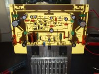
Here you have the German board...it was prepared to accept both ES and ST
versions.
German group has an interesting feature..the supply is on board.... the entire Dx supply, in the reality, it has double Dx supplies...one full wave to the positive and another full wave to the negative.
These supplies were made, mainly, to use two transformers, each one of them having 2 wires in the secondary...or a 4 wire secondary.
About to talk or not to talk, dear niss man.... this one plays music instead of talking.
regards,
Carlos Eugênio
Attachments
This is the audio quality you gonna have at your home
Dx Blame is playing..recording using Nokia N78 cell phone camera..... good audio registration.
YouTube - STEREO.mp4
He is using Aikido tube preamplifier....and sounds resulted very good.
This is the sound you gonna have in your home...build the good one...build the Dx Blame ST amplifier. (or ES)
YouTube - STEREO.mp4
regards,
Carlos
I am proud to say the Dx Blame is now a days famous in Brasil too
This Brazilian forum has 166 thousand guys.
The advertising, made by a forum friend, means..."soon, Dx Blame Amplifier"
Almost a hundred kits already ordered...people is thinking to produce transformer group buy to order transformer from brazilian factories.... Epco condenser factory is in Brazil, also Siemens....enclosure we have several models painted with Epoxi
regards,
Carlos
Attachments

Last edited:
Dear Carlos, I have finished one DX Blame ST amp, I used the PCB layout on the gregs site, and created my own PCB, when I power the amp using 100 ohm series resistance, one on the Negative rail gets really hot and voltage across the resistance read close to 10V, positive side dont get hot, Can you tell me what I did wrong, I used +-25V DC
Thank you so much.
Thank you so much.
It is difficult to point you the cause.... the error...the mistake
for sure there are errors....maybe only one...maybe several.
You should check all your job, transistors position, if NPN is not in the PNP's placa, the resistance values, the solder joints, the condenser polarities...inspecting your board against strong ligth to observe in the transparency mode.
Now is hard job man.....and really only you will be able to find the mistake..i can just give you some courage and enthusiasm to go ahead...to keep you calm saying that soon you will find the mistake.
We use to do mistakes..this is very common.
The VAS transistor, the BD139 inverted can do that... sometimes it burns when inverted ..... but other hundred things can result in that defect, that causes this effect of huge current into the negative rail.
First check if transistors are the correct ones, and positioned correctly in place...watch the board image and see (enhanced image) that you have one small transistor that is mounted facing the other (flat surface facing another flat surface).... also the metal part exposed in some BD139 must face the board input side...the ground track side...... check your drivers and your power....see if you have NPN in the correct NPN place.
If you can, then produce a high resolution picture, using macro mode in your digital camera...natural light... try to avoid shadows adjusting the board considering the sun position....a good focused image can help ...this way i can check with you...do it both sides..and send the full image (do not reduce) to:
carlos.eugênio1951@yahoo.com.
In our forum the limit is 1 Megabyte.... this is not enougth to zoom in and observe details.
Do not use cell phone...pictures from Cell phone serves for nothing in electronics..even the 12 Megapixels ones produce awfull blurred pictures.
regards,
Carlos
Thanks so much for the reply Dear Carlos
Yes I know carlos sorry for the late reply power problems where I live, I will check all the solder joints and Transistors, I will mention some changes in the components I used, because I couldn't find the exact same ones, I'm not sure if they will cause any problems.
for 3K resistors I used 3.01K Metal film ones
for 1N4001 Diodes I used 1N4002
For the Trimpot I used a Multi turn 500R one
I will take a Macro of the PCB and send it to you carlos, thanks for all the help, it would suck if this wont work, I was so waiting to hear DX sound..
Have a good day carlos.
No problems Zeraphine.... this happens with me daily.... in a normal basis
Mistakes is what happens here.... i do not feel impressed you made one....i have made thousands in my life.
Solder...sometimes solder is the problem..... some guys knows how to solder...and others do not know
Shorts caused by solder.... they happens, and sometimes are hard to be seen...clean the board using a brush dampened in Alcohol...it dissolves the solder flux, that brown thing that looks dirty.... we should remove to inspect using magnified lenses.
Board should be inspected against strong light, in a transparency way.... to see if we have interrupted copper lines, or shorts... sometimes missed lines because the heat transference method use to have detached lines that are missed...these lines goes attached to the paper using as base to transfer the image... usually we perceive while soldering...because you gonna solder and no "island" of copper to solder the terminal.
Invert transistors, to assemble wrong way happens a lot.... also the mistake installing NPN in the place we must have a PNP.
Electrolitic condenser invertion happens too...some of them have leakage or inflate, or explode after overheat and acumulate gazes inside.
Wrong resistances also happens.... colour code reading mistakes.
Power supply voltage invertions... this happens a lot too....because of that i use red wire for positive, blue wire for negative and black wire for ground...but even this way you can solder (in the supply) the red wire in the negative side (ahahahahaah!)
Once i have installed 10 ohms in the positive side and 100 ohms in the negative side as protective resistances.... that way i had bigger reading in the negative side.
Have to check.... how to check?
Make a copy from your schematic in your printer...or draw it in a sheet of papper manually.
Then go checking each line of connection and painting red over the papper....red will be checked lines..the present lines...observe the pcboard watching it against the light.... do it looking at the component side... when finished take a look if all lines are red in your schematic....if they are..the board is fine.
Now start to paint red transistors..check them, the model number and the position...check if base is in the right place...if emitter is in the rigth place...as a consequence colector will be in the correct place..the last one does not need to check.
It is time to check each resistance...do not believe in colours and codes....measure the resistance with a multimeter.... you will measure strange values as resistances soldered in the circuit measure less because the circuit....but you may have informations...you can measure much less..but you cannot measure bigger resistance than the expected value....if you have suspection you should lift one side and measure once again....paint resistances checked in the paper
Do the same for diodes and capacitors and condensers..check position, polarity and value.
Your paper will never be all red..because you will find something wrong..will fix and your amplifier will work fine without the need to go on with the red painting method (can be blue or other colour too..ahahahahaah!)
It is just hard work...but the method is safe, the amplifier is not powered,so, no reason to be stressed... calm down, control the frustration, be sure it works because several folks assembled and it really works..be prepared to hard work, sit in you workbench saying to yourself....
-" I will not leave this workbench till i found the mistake"
Switch cell phone off, ask family not to bother you, shut the door, play a soft music to relax and go ahead.
regards,
Carlos
- Status
- This old topic is closed. If you want to reopen this topic, contact a moderator using the "Report Post" button.
- Home
- Amplifiers
- Solid State
- Dx Blame ST - Builder's thread - post pictures, reviews and comments here please.