Please take a look at this seems to be wrong
The potentiometer and the resistor are inverted on the schematic. It makes no difference in the circuit.
Martin.
Hi Steve,
If you look at the attachments I posted above you will see how my board is made.
Thanks Terry. I found a latter post by Byron that shows the connection for R15 that you have in your post. There were also some references to changes made in the initial board design. In any case my boards are the red ones and probably the same as yours.
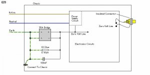
I'm wondering if you have tried the grounding scheme that Doug Self recommends? He wires the input jack grounds to the protected earth ground where the power cord is grounded to the case. If not it would be another thing to try in your quest to silence the hum.
Good hunting.
Steve
Thanks Terry. I found a latter post by Byron that shows the connection for R15 that you have in your post. There were also some references to changes made in the initial board design. In any case my boards are the red ones and probably the same as yours.
I'm wondering if you have tried the grounding scheme that Doug Self recommends? He wires the input jack grounds to the protected earth ground where the power cord is grounded to the case. If not it would be another thing to try in your quest to silence the hum.
Good hunting.
Steve
Hi Steve,
Today I hope to change R8a to main ground and change the gain resistor. If I still have hum I will try again with a wire probe and try bypassing some things.
Yes I did. I also tried taking a test wire, first with a 10R resistor attached to one end and went across all ground points I could reach and when that didn't work I tried it without the resistor and had the same results. The hum only happens when something is plugged into the input.
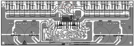
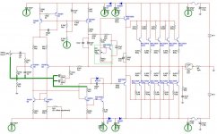
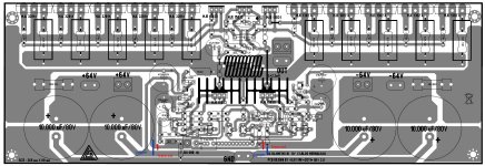
Why not use anti parallel diodes instead of a resistor.The FetZilla uses that together with a 10 OHM resistor but when you've hum you must leave the resistor out.
See at the FetZilla layout near R26
Attachments
Last edited:
Why not use anti parallel diodes instead of a resistor.The FetZilla uses that together with a 10 OHM resistor but when you've hum you must leave the resistor out.
See at the FetZilla layout near R26
Hi Patrick,
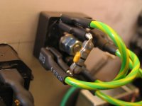
I used an earth-ground loop breaker. Similar to what you suggest. You can see the attachments.
I tried that before I cut the traces and rerouted the stuff that wasn't supposed to be on the lifted ground and I would get a 60 cycle buzz. Now I don't get that but I still have a low hum whenever something is plugged into the input. I am going to re-orient R8A so that it lands on the main ground and change R9 to a higher value and see where that leaves me. Strange that others haven't reported this. I got these boards from you. Did you build it and if so, did yo not hear any hum?
Thanks, Terry
Attachments
Yeah, I don't really "need" any more amps. I'm just building them to learn and I had a 55-0-55vac transformer that I was looking for a home for. For high power I already had a Leach Super Amp and a Honey Badger.
I can easily remove the resistor from the ground loop breaker. It just plugs in.
I can easily remove the resistor from the ground loop breaker. It just plugs in.

At last success. OK I connected R8A to main ground and put 1.2K in R9. The low hum was greatly reduced but there was still a slight 60 cycle hum. So then I pulled the resistor and 100n cap from the ground loop breaker and the 'amp is all but dead quiet. Very acceptable.
I will try to edit a board shot to reflect what I have done to get to this point.
It is strange that with all the amps built on these board that almost no one reported a hum problem. Perhaps, they have done as I have and once it was working they were on to other things. I had some free time since I am waiting on a group buy so it gave me a chance to revisit it. I wonder why it wasn't until recently that someone noticed how many devices were attached to the lifted ground that didn't belong? I must say, I am glad for this amp since it has helped teach me more about grounding and PCB layout. A big thanks to all who have helped with this.
Blessings, Terry
EDIT: BTW, changing R09 is almost unnoticeable in gain. I am driving it from a CD player through a 50K pot, no preamp.
Last edited:
Terry, glad to hear you got it all sorted to your satisfaction. It really is a very enjoyable amp, is it not?
I can't explain why mine is fine without the lifted ground modifications. My loudspeakers aren't particularly efficient (in the 86-90db/w/m) range. Perhaps your loudspeakers are more efficient and that party explains the difference?
I can't explain why mine is fine without the lifted ground modifications. My loudspeakers aren't particularly efficient (in the 86-90db/w/m) range. Perhaps your loudspeakers are more efficient and that party explains the difference?
I don't know either. My 4412 are 90db and the 4425 are 92db. I could hear it on all my speakers. No hum without something plugged into the input. What I do know is that the PCB does not match the schematic. Mine does now except I also moved R17 to the main ground which is not how the schematic shows but someone suggested that it should not be on the lifted ground and it makes sense for it not to be there. It is not a difficult fix and would be a cinch if done during the build. Now that I have the PCB straightened out, the resistors at the RCA may not be necessary but since it sounds really good, I'm leaving them.
The Super A doesn't hum and only the input and feedback share the lifted ground. Using my A/B switch I can't hear any difference between the Super A and the MKII until you get them loud enough for the Super A to start running out of steam.
The Super A doesn't hum and only the input and feedback share the lifted ground. Using my A/B switch I can't hear any difference between the Super A and the MKII until you get them loud enough for the Super A to start running out of steam.
Hi Wayne,
I had to pull the tops of and measure. I have the Super A set at 192mA per rail and +-38.6V. The MKIII is set at 80mA and +-75.5V. They really are just too close to call on my system. Both are crystal clear with great bass.
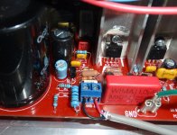
The mod is not difficult. The most time consuming part is pulling the boards out so you can get to it. I am attaching a pic of how I did R8A. I just drilled a small hole through the board to the trace below and swung the end of R8. Sorry, I didn't take any pics of the bottom of the board. I cut the traces just where I show in the other attachment and the jumpers are easy since the traces have exposed copper.
Blessings, Terry
I had to pull the tops of and measure. I have the Super A set at 192mA per rail and +-38.6V. The MKIII is set at 80mA and +-75.5V. They really are just too close to call on my system. Both are crystal clear with great bass.
Glad to read this Terry. On my side, I thought my hum was due exclusively to the wiring that is not perfectly routed in my enclosure. I will do the lifted ground true-ups and see what happens.
The mod is not difficult. The most time consuming part is pulling the boards out so you can get to it. I am attaching a pic of how I did R8A. I just drilled a small hole through the board to the trace below and swung the end of R8. Sorry, I didn't take any pics of the bottom of the board. I cut the traces just where I show in the other attachment and the jumpers are easy since the traces have exposed copper.
Blessings, Terry
Attachments
I'm not sure. I had it higher at one point. Carlos recommends 16mA IIRC. It sounds fine where it is. I'm not sure what it would gain by going higher.
The measured THD for mine declined up until about 56mv bias measured across 2 emitter resistors. Whether that's audible compared to lower bias levels is anyone's guess.
Nice work Terry on the hum problem. I'll be making the same changes as soon as I get my replacement amp ready to go online. BTW I think back when the thread was more active there were several reports of low level hum being experienced by builders. At this point there seem to be only a few builders still tuned in.
Happy New Year
Steve
- Status
- Not open for further replies.
- Home
- Amplifiers
- Solid State
- Dx Blame MKIII-Hx - Builder's thread