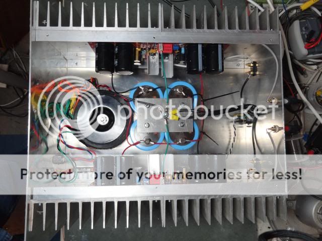
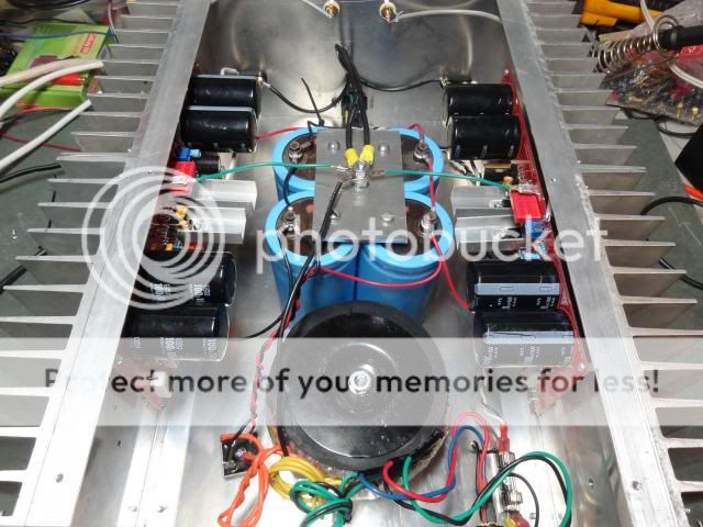
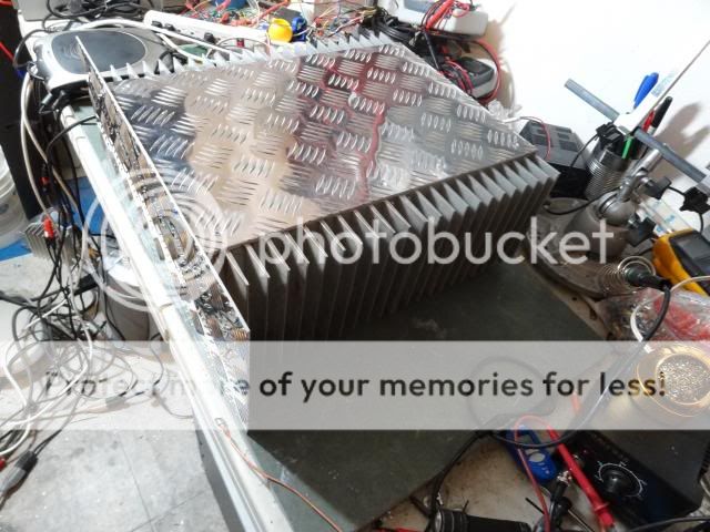
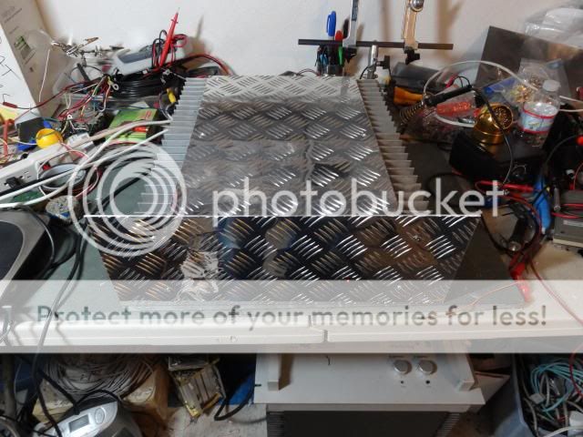
Oh!... congratulations and my best wishes to your baby girl
I will sleep...the computer is already uploading and the video gonna be available in more one hour.
The computer will be on.... and uploading while i am going to the bed to sleep.
Here is the link:
MKIII Current increases while overheat - YouTube
regards,
Carlos
I will sleep...the computer is already uploading and the video gonna be available in more one hour.
The computer will be on.... and uploading while i am going to the bed to sleep.
Here is the link:
MKIII Current increases while overheat - YouTube
regards,
Carlos
This kind of amplifier, able to high power is not something easy
to cool down, reason why i was, always, very resistant to accept people operating it in class A.....many guys asked that and i always used to denny..because it is very difficult to keep it stable when we have drivers into the main heatsink.
If you read the thread, the original thread, you gonna see i suggest folks to adjust the bias current just to have a very small ammount of current into the output transistor...less than milivolt measured over the resistor that is in the power transistors.... as we have several transistors, them 10 units will generate some heat even being small the current.... this also produces more than 4 miliamperes into each of the power transistors, this is already approximately 400 milliwatts to each one of them... 4 watts of heat.
If we try the lowest possible distortion, in special avoiding the crossover points, when the transistors switches (Class A) then we have to inject something alike 20 to 30 milivolts into each emitter resistor....if they are 0.22 ohms, then we have almost 10 watts into each power transistor..this represents 100 watts of heat and many watts into Class A operation....
If the resistor is 0.47 ohms, then the problem is smaller.... reduces to almost 5 watts to each power transistor and the heat goes to 50 watts (approx.)
I suggested people to "give it a try"... but for testing purposes.... while making comparison and operating the MKIII into it's best operational point related audio quality and distortion...but for sure it is not to operate this way, as this amplifier was calculated to operate in Class AB, where the iddle current into the power transistors is small.... the idea is to increase, to listen and test outside the most stable point of operation (less than 1 milivolt measured over the 0.22 ohms power emitter resistor)...as people, naturally will perceive it too much hot and by themselves will reduce the stand by current to avoid to overheat your listening room (hehehehe).... the equipment becomes a ambience heater...good to hard winter days if you increase bias and make it work Class A.
I have asked people to use huge heatsinks...but no one could use them as they have not found a real big ones...so.... even the best ones made are using very small heatsinks to an amplifier able to produce huge ammounts of power in Class AB....now imagine some toy heatsinks with this amplifier operating Class A!.
Some guys uses big heatsinks but with few fins...small area to the air,.. others are in inverted position related to optimized convection cooling...the ones used heat tunnel had better results as fan is helping to cool the heatsink down.
To the ones wants to operate with higher bias, or higher stand by current, then the milivolt i told you..or 4 miliamperes to each power transistor (approx.), then i suggest to lift the drivers..to put them out of the main heatsink and to install heatsinks on them...video shows you, clearly, the result of these drivers overheating.
More modern designs are not using drivers on the main heatsink anymore....this one, as i have suggested very small current and really huge heatsinks (no one managed to find a really huge heatsink in my point of view) then i perceived in my home tests, operating 8 and 4 ohms, the sittuation as controlled....but..in the reality, i have not the huge power transformer or supply needed to test it full power over 2 ohms.... this way, i do not know exactly the behavior under such condition.
Increase of stand by current when the amplifier overheat is normal..this happens..and when it cool down it returns to the correct current....if you have proper heatsink or cooling fan, then you will not have all that drift of stand by current.
My suggestion was, i am repeating to let it clear friends, to increase the current, for some minutes, in order to make comparison with other amplifiers...optimizing the unit...but it is not to be used this way and all time long, as a new adjustment, for life long, as this is Class A.... so, a huge stand by current...when the amplifier was created, conceived and tested to operate in Class AB...and if we force it to operate outside the limit it gonna produce problems..for sure it will.
Our car was made to 6 passengers and some luggage...try to put 13 passengers and some engine in the rear trunk.... your car will overheat, the suspension will fail, the engine may fail too.
Please, MKIII builders...watch this video:
MKIII - Current increases while overheat - YouTube
It is not the MKIII, it is a Super A tuned to small current due to my small heatsinks..but the behavior or the heating effect happens in any audio amplifier under such condition.
regards,
Carlos
Last edited:
The current Terry adjusted, if over a 0.22 ohms resistor
forced the amplifier to dissipate 150 watts of heat!
Terry cooling fins into the heatsink is one third the needed quantity, also the heatsink position is not the good one for convection cooling.
I do think this was a real torture and i am happy the amplifier survived....my expectation under such conditions it to have a tragic breakdown.... i am very surprised it survived by 15 minutes long...if you asked me my expectation of how long it would survive...i would say 3 minutes.
Because it is not only the 150 Watts of heat caused by the iddle current...we have also, and together, the audio power that increase current and he was, for sure, playing 20 watts per channel peak (at least because his speaker efficiency)...and this produces a huge heat too.... watching the heatsink position, inverted related the optimum condition, or at least 180 degrées off, and considering a very few fins in his heatsink...i am very surprised it could play 15 minutes and survive under such condition.
In my fast calculation, using my skills destroying amplifiers, i would say Terry had 250 watts of heat in to the peaks of his 20 watts music playing...to each channel..and this would need 25 fins of aluminum, measuring each one of them 4 inches side (squared), in the correct position and assembled into a long thick blade of aluminum (the base) to dissipate each channel power..... and you see his heatsink has few blades.
Terry heatsink, in my fast calculation and fast evaluation by eye, can face continuous 200 watts but in the correct position, and it is not in the correct position... so.... it cannot cool down the amplifier under the operational condition it was operating.
It would need, at least, twice the fins it has and the heatsink would have to operate in the correct position to face Terry amplifier operating with this stand by current and listening audio of 20 watts RMS.
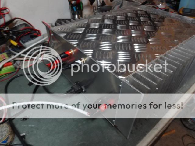
If we compare Terry heatsinks with teeth inside someone's mouth...then his heatsink has some missed teeth (fins) alike the image .
.
Yep..they are fine...huge heatsinks...very nice..but there are so few fins on it......
regards,
Carlos
forced the amplifier to dissipate 150 watts of heat!
Terry cooling fins into the heatsink is one third the needed quantity, also the heatsink position is not the good one for convection cooling.
I do think this was a real torture and i am happy the amplifier survived....my expectation under such conditions it to have a tragic breakdown.... i am very surprised it survived by 15 minutes long...if you asked me my expectation of how long it would survive...i would say 3 minutes.
Because it is not only the 150 Watts of heat caused by the iddle current...we have also, and together, the audio power that increase current and he was, for sure, playing 20 watts per channel peak (at least because his speaker efficiency)...and this produces a huge heat too.... watching the heatsink position, inverted related the optimum condition, or at least 180 degrées off, and considering a very few fins in his heatsink...i am very surprised it could play 15 minutes and survive under such condition.
In my fast calculation, using my skills destroying amplifiers, i would say Terry had 250 watts of heat in to the peaks of his 20 watts music playing...to each channel..and this would need 25 fins of aluminum, measuring each one of them 4 inches side (squared), in the correct position and assembled into a long thick blade of aluminum (the base) to dissipate each channel power..... and you see his heatsink has few blades.
Terry heatsink, in my fast calculation and fast evaluation by eye, can face continuous 200 watts but in the correct position, and it is not in the correct position... so.... it cannot cool down the amplifier under the operational condition it was operating.
It would need, at least, twice the fins it has and the heatsink would have to operate in the correct position to face Terry amplifier operating with this stand by current and listening audio of 20 watts RMS.
If we compare Terry heatsinks with teeth inside someone's mouth...then his heatsink has some missed teeth (fins) alike the image
Yep..they are fine...huge heatsinks...very nice..but there are so few fins on it......
regards,
Carlos
Attachments
Last edited:
Zimmer is developing a switching mode power supply
SMPS to use together Dx amplifiers..... he gonna ship to me for testing.... we have not achieved the power we want...for a while.
The owner of the diySMPS forum, Mr. Sami, that has expertise in switching mode power supply, have designed his own supply and said the sound was cristal clear together the MKIII...here you can see the movie:
20111224014703 - YouTube
I will post some pictures....from Cannonica, from Lumieux from Junie and from MJ777.... Lumieux is the one made the best one...you see his workbench with a lot of tools.
regards,
Carlos
Attachments
Thanks for the video Carlos. Very informative. I am not interested in running hotter than necessary. I couldn't find it yesterday but I know I had read somewhere that the amp should be adjusted to 16mV across the emitters. That is why I picked that setting. I know that the position of the heatsinks in my picture is not optimum. It was strictly for testing. I continually touched the heatsinks and transistors with my fingers during the test to make sure nothing got too hot. What you show in the video is exactly what my amp did. The current just ran away like that. I will reduce the bias as you have suggested and I will also move the drivers to separate heatsinks.
By the way, my heatsinks measure 6" x 17" x 2" with 20 each 1.75" x 6" x .125" fins. They are larger than the heatsinks I used for the Honey Badger and it runs very cool.
I will make the changes and report back tomorrow. I am getting the evil eye from the Mrs to get off the computer and get ready for the wedding.
Blessings, Terry
Yes... 16mV was pointed as an option during comparison
But after the comparison finishes, it is a very good idea to return the adjustment to the standard 1 milivolt maximum into the emitter resistors.
It is a good idea to remove the drivers from the main heatsink..then you will be rid to be monitoring temperature with your finger tips.
regards,
Carlos
But after the comparison finishes, it is a very good idea to return the adjustment to the standard 1 milivolt maximum into the emitter resistors.
It is a good idea to remove the drivers from the main heatsink..then you will be rid to be monitoring temperature with your finger tips.
regards,
Carlos
Ok, so I had a few minutes today and pulled the drivers from one board and moved them to the top and put them on their own heatsinks. Just to test, I set the bias to 16mV across one emitter. I let it run for a while. I had to continue to adjust the bias lower as it ran to keep it at 16mV. I continued to monitor the heat as it ran. The only thing that got hot were the VAS and drivers.s The outputs got barely warm. I will do some more testing tomorrow. I will set both channels to the same bias and see which hold their bias better. I'll report back.
Blessings, Terry
Blessings, Terry
VAS cannot be hot too
If it is hot to the touch, then increase heatsink size/capacity
hold it tight

 with two fingers pressing it, one finger against the other,,, you may count thousand and one, thousand and two....slowly till four...if you can keep your fingers there and not smelling barbecue....then it is all right
regards.
Carlos
If it is hot to the touch, then increase heatsink size/capacity
hold it tight


 with two fingers pressing it, one finger against the other,,, you may count thousand and one, thousand and two....slowly till four...if you can keep your fingers there and not smelling barbecue....then it is all right
regards.
Carlos
Hi Carlos,
THe VAS is not too hot to touch. My point was that both the VAS and Drivers are hotter than the outputs. The outputs at 16mV are only barely warm. I can't see them causing a problem for the drivers if they share the big heatsink. I believe I may have discovered the reason the one side had a runaway. When I removed the drivers from the main heatsink, I could see that one of them was not making good contact with the heatsink. The thermal paste was not completely compressed. I believe the leads may have been holding up the foot of the transistor even though the mounting bolt was tight. I am going to place them back on the main heatsink and make sure they fit tightly. I'll report back.
THe VAS is not too hot to touch. My point was that both the VAS and Drivers are hotter than the outputs. The outputs at 16mV are only barely warm. I can't see them causing a problem for the drivers if they share the big heatsink. I believe I may have discovered the reason the one side had a runaway. When I removed the drivers from the main heatsink, I could see that one of them was not making good contact with the heatsink. The thermal paste was not completely compressed. I believe the leads may have been holding up the foot of the transistor even though the mounting bolt was tight. I am going to place them back on the main heatsink and make sure they fit tightly. I'll report back.
Oh!... i see Terry....yep...this happens
These small things happens with us...people that build things....we do a lot, and as a consequence of so many amplifiers built, we produce a lot of small mistakes too.
The ones build anything..these ones do not make mistakes...this is for sure.
regards,
Carlos
These small things happens with us...people that build things....we do a lot, and as a consequence of so many amplifiers built, we produce a lot of small mistakes too.
The ones build anything..these ones do not make mistakes...this is for sure.
regards,
Carlos
Last edited:
If it is hot to the touch, then increase heatsink size/capacity
hold it tightwith two fingers pressing it, one finger against the other,,, you may count thousand and one, thousand and two....slowly till four...if you can keep your fingers there and not smelling barbecue....then it is all right
regards.
Carlos
What if with sauce, still no good ....
Last edited:
Hi Guys,
Alright, I'm reporting back. I moved the drivers back to the main heatsink and made sure they had full contact with the surface. I put a BD139 back for the VBE. I got everything hooked back up and set it to 32mV across a pair of emitters. I let it play for over 1/2 hour at a pretty good level into my JBL 4312's which are 8ohm. The heatsink gets just a few degrees above ambient. I believe I could go quite a bit higher on the bias without too much worry but I don't know if it needs it. A few days ago, I had it playing into 4ohms and I believe I had the bias set at 50mV per pair. After about 10 minutes it blew the fuses on the left channel. I think I had 6A fuses in there. Anyway, I'm thinking it may have some trouble with 4ohm with the +/-76V rails and that high of bias. I have to get some more fuses before I try running it on 4ohm again.
I did A/B it with the Honey Badger and there is almost zero difference in sound. I would be surprised if someone can hear the difference. That is a good thing by the way.
Blessings, Terry
Member
Joined 2009
Paid Member
I plan to do that in the near future. I just got some 50K pots to make an A/B volume box to get a more colorless input for the amps. As soon as I finish mounting these last 4 amps into cabinets, I plan to do some serious comparisons between them. I will have my son help in the comparisons as he has younger ears. Should be fun.
Blessings, Terry
Blessings, Terry
Sorry, I missed this. I got the heatsinks from a guy who Crispycircuit turned me on too. I think he sells on ebay but gave me a better price than the ebay price. They are 6"x9"x2". I used two per side. They required a little modification. Still a good deal and so I bought more to use for the SKA and VSSA.Hey Terry,
Did you get those heatsinks from ebay or you found a local supplier?
Blessings, Terry
- Status
- This old topic is closed. If you want to reopen this topic, contact a moderator using the "Report Post" button.
- Home
- Amplifiers
- Solid State
- DX Blame MkIII - 2013 builders thread.


