"PE" is "Protective Earth" in Britain. About the same as System Ground or Equipment Ground or Safety Ground.
For more, start at about page 10:
http://www.audiosystemsgroup.com/SurgeXPowerGround.pdf
For more, start at about page 10:
http://www.audiosystemsgroup.com/SurgeXPowerGround.pdf
Last edited:
It is Protective Earth which is the third pin in the wall outlet that is needed for safety. Calling it System Ground/Equipment Ground is one of the reasons things get mixed up ! If only the names would be used consequently there would not be so much confusion. As said before there are cultural/regional differences too. The article is a good read about how things work but I could not find a practical example /schematic how to separate grounds but I lacked the time to read it thoroughly. I did find this explanation why signal GND and PE should be not be directly coupled:
Radio frequency noise may be coupled onto the power line (or onto the equipment ground) by switch-mode power supplies, especially those that are poorly designed. This noise can cause serious interference to radio reception (AM and FM broadcast tuners, wireless mic receivers, hearing impaired systems). If this noise is impressed onto cable shields, it could couple into signal circuits by the mechanisms of pin 1 problems, SCIN and capacitance imbalance in balanced circuits, and IZ drops on the shield of unbalanced wiring. Power supplies and battery chargers for large consumer and commercial equipment such as power tools, electric blankets, low-voltage lighting, golf carts, etc. are notorious sources of RF noise. Ironically, this noise is coupled onto equipment grounds by the capacitors within line filters that most national governments require to be built into electronic equipment!
Last edited:
role of PE (protective earth)
The role of PE in electrical equipment is to keep the equipment "safe" for humans in the event of an insulation failure. For example, should the “basic” insulation that isolates the primary windings of a transformer fail and short to its core or frame, the chassis will remain at a safe potential because the chassis is earthed via the safety earth connection.
If insulation meets certain requirements (physical thickness and voltage breakdown) it can be classified as “reinforced” and the equipment would not be required to have a PE connection.
Often, equipment will have both types of insulation. Basic insulation is used to isolate the primary components from the chassis and the secondary windings will have reinforced insulation from the primary. The power supplies in our computers are usually built this way. The output of the secondary may be connected to the chassis as a way to establish a voltage reference to other equipment.
Understand that in addition to “voltage” hazards equipment may also pose “energy” hazards and connecting the secondary output to the earthed chassis may still be required. Equipment must be designed such that a failure of any component does not create a hazard, either a shock hazard, an energy hazard or a fire hazard.
Many pieces of audio equipment are built with reinforced insulation between the AC mains (primary windings) and the secondary windings such that a low impedance connection to PE is not required. This allows the “ground” of the audio path to referenced to PE with a high impedance. There appears to be a consensus that this approach is advantageous for sound quality.
Cheers,
Kevin
I think you are referring to double insulated standards covered by ClassII regulations.The role of PE in electrical equipment is to keep the equipment "safe" for humans in the event of an insulation failure........
............Many pieces of audio equipment are built with reinforced insulation between the AC mains (primary windings) and the secondary windings such that a low impedance connection to PE is not required. This allows the “ground” of the audio path to referenced to PE with a high impedance.
I believe the consensus of opinion is that we as a group are not competent to design and build and test such equipment to be able to guarantee that all will pass the ClassII regulations.
We usually only build ClassI equipment that has a permanent connection from PE to Safety Earth and that all exposed conductive parts are connected to the Safety Earth.
We do have an outright ban on discussion of non-isolated mains powered equipment. I don't think that ban has been extended to include discussion of ClassII equipment.
Last edited:
safety & thread topic
Don't take this wrong as safety issues are number 1 when messing w/power: I'm looking forward to this thread getting back on track.
I've seen several threads on another forum spend 2-3 pages "off topic," because, unknown to OP, the OP brought up a controversial subject, wire & ICs in those threads.
thnx tony
Hi all.
Many thanks to everybody for their answers and advice. I've been doing a lot more homework and there appear to be two predominant designs which appear again and again..
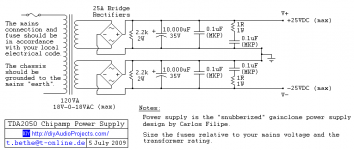
Design 1
This is the design I'm biased towards and is the one recommended on numerous sites including tnt-audio...
-Dual secondaries
-Dual rectifiers
-Negative from rec 1 and positive from rec 2 combined to produce earth connection
-smoothing capacitors snubbed to reduce noise
Design 2
-Single secondary, with transformer centre tapped to produce earth
-Single rectifier
In either case the resulting + & - rails are then split to feed the amps.
Obviously design 2 has the advantage of using fewer components and is therefore cheaper, however as far as I can ascertain design 1 produces the cleanest supply.
As capacitors and rectifiers don't represent a huge outlay of money, and if design 1 does prove most beneficial, then it would seem to make sense to go down that route.
Other techniques I'm researched include snubbing the rectifiers, either all connections or just the AC inputs, and also snubbing the mains switch to eliminate the 'power-on popping' and to apparently reduce the chances of arching.
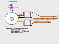
Image 1 is what looks to me to be a great example of design 1.
What do you think?
John.
Many thanks to everybody for their answers and advice. I've been doing a lot more homework and there appear to be two predominant designs which appear again and again..
Design 1
This is the design I'm biased towards and is the one recommended on numerous sites including tnt-audio...
-Dual secondaries
-Dual rectifiers
-Negative from rec 1 and positive from rec 2 combined to produce earth connection
-smoothing capacitors snubbed to reduce noise
Design 2
-Single secondary, with transformer centre tapped to produce earth
-Single rectifier
In either case the resulting + & - rails are then split to feed the amps.
Obviously design 2 has the advantage of using fewer components and is therefore cheaper, however as far as I can ascertain design 1 produces the cleanest supply.
As capacitors and rectifiers don't represent a huge outlay of money, and if design 1 does prove most beneficial, then it would seem to make sense to go down that route.
Other techniques I'm researched include snubbing the rectifiers, either all connections or just the AC inputs, and also snubbing the mains switch to eliminate the 'power-on popping' and to apparently reduce the chances of arching.
Image 1 is what looks to me to be a great example of design 1.
What do you think?
John.
Attachments
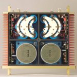
Super Cool Paint Job Dude !
Hi John
Your amp looks way cool.
I'm thinking of doing a 'Jackson Pollock' type paint job on my Thorens plinth restoration.
Have you got any more pics ?
Do you like John Squire from the roses guitar paint jobs ?
Here's a cool PSU layout.
I Never use fuses anywhere personaly, except for the 1A in the plug top.
Simon

What do you think?
John.
Hi John
Your amp looks way cool.
I'm thinking of doing a 'Jackson Pollock' type paint job on my Thorens plinth restoration.
Have you got any more pics ?
Do you like John Squire from the roses guitar paint jobs ?
Here's a cool PSU layout.
I Never use fuses anywhere personaly, except for the 1A in the plug top.
Simon
Attachments
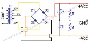
Hi,
that use of paralleled bi-fillar wound secondaries is OK.
The use of separate transformers to create the opposite polarities is OK.
The PSU will work well.
Try changing the grounding at the output of the PSU.
I suggest you move the earth symbol to one of the tails of the multi-tapped Zero Volts connection. Now move the three spare tails to where the earth symbol was.
This then allows the pulsing charge currents to stay in the loops formed by the transformer/rectifier/smoothing caps. The amplifier currents then pass around loops in the amplifier. The only connection between the PSU and the Amplifier is that single length of wire. The charging pulses do not pass along the wire. Only the supply ripple passes to the amplifier.
Try to keep current loops separate from each other. Try not to let one wire share currents from two different loops/circuits.
Hi John
Your amp looks way cool.
Hi Simon. Thanks but that's not actually mine, I was simply using it an an example of the PSU layout I'm planning on using!
I'm thinking of doing a 'Jackson Pollock' type paint job on my Thorens plinth restoration.
Have you got any more pics ?
Do you like John Squire from the roses guitar paint jobs ?
Yes and I love the Roses! Squire is a guitar god!
Here's a cool PSU layout.
I Never use fuses anywhere personaly, except for the 1A in the plug top.
Serious? Isn't that a bit risky?
Simon
"Fools Gold"
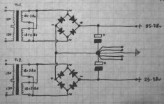
Design 1
Yo Holmes, H'w y'r doon bro.
Indeed..., guitar god, most def.
I struck gold today, and hit the motherload !!!
Just got back from my most successful skip-dive EVER !
The cell phone companys skip, outside their local mast refurbishment, was
positively briming full of cool goodies for the diyAudio freak !
I'll post a photo of my haul in your thread when I've stripped it all down.
There was a transformer there so big that I couldn't lift it, am most def going back tommorow with a mate of mine to help me get it out.
Just what I need to clone an ARMAGEDDON power supply for my turntable refurb. This m'fu' makes the original Armageddon power supply look like a wall wort !!!
Anyway, just sat down with a Java Sumatra and the Roses "Fools Gold" 12 and reviewed the thread from the beginning. Thought I might just throw my penny worth in to mix up the pot a bit.
Before I do, I'd like to say that none of my diyAudio projects have ever harmed children or pets (accept for excessive SPL's that is), although I did discover a dead spider inside one once, but having not carried out a post-mortum, I'm afraid I can't confirm whether it died of electrocution or natural-causes.
You don't mention in the thread John, what type of amp you want to build.
I can guess what it might be from the transformer and secondry volts, by I won't, as a power supplies a power supply no-matter what gets hooked up to it, we could make a perfect power supply to run a light bulb, but we don't usually bother.
Have to say though, if I had a whacking great 500va 40v torroid, I'd make a fan-cooled 'Son Of Zen' v6a, but that's just me.
There are lots of different ways a symmetrical power supply can be made, but in my humble opinion there is only 1 right way; and yes, that way is design #one in your post #26.
Ignoring the twin transformers, which can just be thought of as twin secondarys, the schematic is exactly the same as the one in my own post.
Visualy it looks different, and I would say that the clearest or purist (form follows function) way to draw the schematic is the way I drew it.
Drawing the individual diodes that form the two rectifiers, more clearly illustrates how the circuit operates, and you will notice that the second rectifier has been depicted reversed, which allows the schematic to be drawn symmetricaly in a visualy more helpful way.
Electrical symmetry is also visual symmetry.
There have been lots of different theoretical PSU layouts thrown around here, but what hasn't been covered are the very simple reasons WHY a PSU should be constructed as in my schematic, and WHY all the other layouts, although they would work are in fact unsuitable.
The other obviously important aspect which hasn't been covered, is once the WHY is understood, HOW should this schematic be implemented in reality and WHAT components might be the most suitable for the 'perfect' power supply (which of course dosen't exist).
Earthing has also been widely covered but not WHY it's important, and in fact a lot of what has been said has not used the best terms to make this issue clear.
Earthing is simply connecting the yellow/green wire to the chassis, and of course insuring that ALL chassis parts have continuity to earth (anodised Aluminium, painted screws & panels, handles and other removable parts are often unknowingly left unearthed).
This earthing is not only important for safety, but is important for 'screening' the audio circuit from RFI, and dumping any RFI picked up into the mains earth and not the power supply.
The other 'earthing' that has been mentioned, I would prefer to in fact call
'grounding'. Earthing and grounding are not the same thing.
The audio circuit (and I'm totaly with Jean Paul on this one) does not have to be connected directly to earth, and for the most part is totaly undesirable to do so.
The best way to think about the audio ground in my view, is as the part of the circuit where you will find zero volts.
This is on the central rail of the power supply, this of course is also imperfect as like it or not there will always be a few milli-volts around, where idealy in the 'perfect' world there should be none.
The central rail of our PSU is essentialy 'floating' and what we don't want is for it to be connected directly to the chassis earth, which if it were, would allow RFI, transient voltage spikes and who knows what else, to be injected directly into our power supplies nice clean zero volts central rail.
We have already established that our zero volt rail is not perfect and will have very small (yet significant) voltages superimposed on it.
However there is one 'singular point' on the central zero volts rail where we will be as close to ZERO as we can get, and this is where the 'star ground point' should be located.
There are two principle reasons for the rejection of all the other PSU schematics mentioned.
One is the connecting of reservoir (or smoothing) capacitors in series with one-another (that effectively doubles their resistance, and raises their 'impedance'), causing the power supply to loose 'speed' and creating unnecessary noise, which is the lesser of the two evils.
The other is that the rejected schematics prevent us connecting the star ground point in it's optimum position (which increases the amount of milli-volts on our already slightly imperfect zero volts central ground rail), creating unnecessary noise.
The single rectifier, centre tapped topology suffers both these problems.
The double rectifier centre tapped topology, the first in this thread, suffers both these problems.
The double rectifier, twin secondary topology, suffers neither of these problems.
So why isn't it always done like this ?
It costs the price of 4 extra diodes to do it !
So where is the optimum position for our zero volts star ground point ?
This for some reason makes me think of our (I'm sure 'imperfect') theory that the Universe began 13.7 billion years ago, as an infinitely dense mass, at an infinitely singular point in space.
The 'perfect' star grounding point may be thought of like this.
The star ground point or 'point zero' in the physical reality of constructing the power supply should be placed as close as physicaly possible to the junction between the terminals of the following 4 components:-
*The negative pole of the positive rectifier.
*The positive pole of the negative rectifier.
*The negative pole of the positive capacitor/s
*The positive pole of the negative capacitor/s
That almost sounded confusing.
Looking at the schematic, where earlier we depicted the negative rectifier
reversed, enableing the previous schematic to be 'unraveled' and shown
symmetricaly.The schematic is drawn to more clearly illustrate the 'function' of the circuit.
Now in your minds eye warp it and stretch it again, so that all 4 points come together at one centre, this is the ideal 'physical' layout of our power supply.
It's probably worth redrawing it in this way just to see how it looks when laid out with real components, or if you have the real components, just lay them out to closely form the star ground singular point.
Just to reiterate, the star ground should not be connected to the chassis.
Here's an example of this concept put into practise.
Have a look at some of the diyAudio members photos of their amps, you will often see copper 'bus-bars' screwed to the terminals of the reservoir capacitors. This is good, it ties all the reservoir capacitors together very closely useing solid single pieces of copper with 'zero' resistance.
Now look some more (and you don't see this as often), the people who are really on top of the game, find an ingenious method to mount their rectifiers on top of the bus-bared capacitors, and this is also where you will see their star ground point, all at a singular spot.
It's also worth at this point having a quick look at the real components that make up the power supply, the unnecessary and undesirable use of secondary fuses and some very simple ideas to improve safety, without, degrading performance.
I can only say how I would build this power supply, I believe countless others would agree, as all these concepts and components are well established for the purpose, a few will inevitably disagree.
If the transformer is run to its maximum rating of 500 Watts (which is in most instances unlikely) it will draw 2.17 Amps and therefore a 3A fuse in the plug top will be needed.
Now you need a plug to put it in.
You can get very pretty mains plugs from your friendly local 'Hi-Fi' dealer, who's eyes light up and flash $$ signs at the mere thought of them.
They are made of tongue twistingly named plastics that no ones ever heard of, but have been extensivley tested in deep space by NASA.
They are often plated with exotic metals with amazing properties, proven by quantum science using atom smashing particle accelerators.
The cheap ones are just boreing old bog standard 24k gold, and could look fairly cool with a matching neck chain and watch.
But seeing as your just about to stick it in a £2 wall socket that the children have forced jam into in a suicidal bid to get electrocuted, and that's also probably clogged up with pet fur; I don't bother, and just get mine from the latest skip-dive, leaving me with 200 quid or so in my pocket that I can spend on a weeks knees up in Benidorm.
Mains cable. Much the same as above, accept the dealer's eyes are like this now:- $M$M.
I use 0.75mm Sq. shielded SY type control cable, as used by utilitarian non space traveling industrial robots that weld cars together.
For the technicaly minded the cable has three 6amp cores of 24/0.20mm annealed copper, two seperate layers of PVC insulation and galvanised steel braid shielding (which should be connected at the wall socket end only) to withstand the rigours of the Trabant production line. The cable has an OD of 7.8mm, is extremely resistant to chewing by children & pets, and is available from CPC #CB08727 at £0.56p +VAT / metre.
Chassis plug & socket. I'm going to have to go for the 'Neutrik tm' connectors here, and indeed for all of the amps connections, including the wonderful Neutrik 'Speakon' loudspeaker connectors, for 3 reasons:-
1. I hate cuting out IEC shape holes in chassis.
2. All connector types (mains, RCA, XLR, USB, ethernet, speaker) fit in the same size mounting hole of 24mm OD with two M3 fixing screws, they can all be mounted from the front or rear of the panel, and therefore can be removed without de-soldering, with PCB's etc. still attached. And of course the mounting holes all being the same size means yesterdays mains socket hole can be tommorows RCA one. Brilliant !
3. The quality of every Neutrik product is second to none, and I can't grumble about any aspect of the range, not even the price.
Cable Plug - CPC #CN04055 £4.29p +VAT each
Chassis Socket - CPC #CN04057 £1.99p +VAT each
Mains Switch. That must mean we're nearly on to fuses, and since we don't want any annoying or sound degrading fuses in our chassis or lovely clean power supply, we will start as we mean to continue.
In a word, or two, Rocker Actuated Thermal Circuit Breaker Switch.
In this case we'll fit a 3amp Double Pole Double Throw version that has high in-rush current capability and sealing to IP40 standard.
In case the amp is for use out-side in showery conditions or the pets keep licking it or the children try pouring Ribena into it in another foolish bid for annihilation, our fuse-less fused switch can be upgraded to IP65 standard for a small additional cost of £0.89p +VAT.
My favorite one of these is CPC #FF02129 £7.99p +VAT each
They come in an almost sombre monochrome white with black bezel, and won't upstage the dazzlingly bright ON LED on the front of the amp.
As with the Neutrik chassis socket, terminals are push on spade connections which can be totaly insulated.
Transformer. Get a massive great huge one and insulate the primarys.
Diodes. The Space Egg Corp. feels that along with IEC plugs, fuses and prehistoric 4mm binding posts the humble silicon rectifier diode should similarly be left to the history books.
Enter the new modern efficient streamlined and non RFI generating Schottky diode, the 'perfect diode'.
Apart from kindly not chucking out handfulls of RFI at your lovely clean power supply and having a go at saturating your massive huge transformers core. They also kindy don't rob you of precious voltage (only 0.75 volts on the sleek 'MBR20200CTG' 20amp 200volt model) and waste it as heat. Furthermore their not expensive, and all the money you save not having to buy loads of capacitors to snub reverse recovery kickback, you can spend on something more useful or justgo to the pub.
As above CPC #SC07395 £1.60 each or 10 @ £0.99p each +VAT
Reservoir Capacitors - "Let's go to work!" Our tiny little electron finally arrives at the front-line slightly exhausted and very agitated after it's long journey from inside the nuclear power-plant along miles and miles of cable on huge HT towers, wizzes through the transformer at the local substation, speeds through even more miles and miles of cable, through the 1.5 metres
of £300 Hi-Fi dealers cable (if you didn't spend the week in Benidorm); And at last reaches our reservoir capacitors where it chills out for a moment or two before wizzing off again all calm and refreshed to make melodious music in our amp.
Size isn't everything. When choosing capacitors big is not necessarily best.
The size of the capacitor in uF's is one thing, what we're really interested in is it's resistance or ESR which should be as low as possible and indicates it's ability to pass energy freely, and it's 'Ripple' rating which should be as high as possible and indicates it's ability to smooth energy freely.
If we join 2 capacitors together in series we double the ESR, which is bad. If we join 2 capacitors together in parallel we halve the ESR which is good.
Likewise we also gain a higher 'Ripple' rating which is good. Where it gets
interesting for example is if we join 100 capacitors together in parallel, it seems like we are getting something for nothing for a change, we can divide the ESR by 100 which is very good, and at the same time multiply the 'Ripple' rating by 100 which is also very good. The ideal 'Perfect' power supply doesn't exist, but if it did it would matterialise energy out of thin air, have no ripple to deal with and supply energy freely without resistance.
The multi parallel capacitor power supply is nothing new, but is regarded by some as a significantly worth while step towards the 'perfect' power supply. Perhaps why we don't see it implemented more often is that the cost is slightly higher, the effort to assemble it is more and the space needed for it is more.
But hey try it out yourself, get your own favorite brand of can electrolytic
capacitors figures and do the maths up against an equivalent volume in uF's of a quality small form capacitor such as the Panasonic FM, check that the ESR and ripple figures of the capacitor are both quoted at the same frequencys (if not there is a conversion table for this in the manufacturers datasheet), and be amazed by just how far the resistance goes down and the ripple rating goes up.
Then build it and see what it sounds like.
We could embelish the power supply a bit by fitting a decent mains filter (RS Components have lots of good ones to choose from, or diy your own), a thermistor could be put in series with the live transformer primary to stop any 'turn on thump' or we could add further levels of smoothing. But the basic power supply with good layout, good grounding, good components and good construction will function well as it is.
As the amps not built yet connect up a light bulb and enjoy noise and ripple free light.
Hope that helps with the amp build
Cheers Simon
Hey Simon!
I'm good thanks, and many thanks for your essay and for your diagram!
You've basically confirmed what I was hoping, that the dual secondary/dual rectifier circuit is the way to go.
I totally appreciate what you are saying about not connecting the power supply ground and the amp ground to the same place. However I'm a little confused. To quote from your post:
"The star ground point or 'point zero' in the physical reality of constructing the power supply should be placed as close as physicaly possible to the junction between the terminals of the following 4 components:-
*The negative pole of the positive rectifier.
*The positive pole of the negative rectifier.
*The negative pole of the positive capacitor/s
*The positive pole of the negative capacitor/s
That almost sounded confusing.
Looking at the schematic, where earlier we depicted the negative rectifier
reversed, enableing the previous schematic to be 'unraveled' and shown
symmetricaly.The schematic is drawn to more clearly illustrate the 'function' of the circuit.
Now in your minds eye warp it and stretch it again, so that all 4 points come together at one centre, this is the ideal 'physical' layout of our power supply.
It's probably worth redrawing it in this way just to see how it looks when laid out with real components, or if you have the real components, just lay them out to closely form the star ground singular point.
Just to reiterate, the star ground should not be connected to the chassis."
I understand the principle that you're putting across but I'm confused as to where exactly the 0 volt rail (point zero) is grounded?
I've drawn a diagram below to illustrate how I think this would look using bus bars, which are an excellent idea.
I'm guessing that where those four 'magic' points meet is what you are referring to as 'point zero' which is this case would be the middle bus bar on my diagram, or the large dot in between the capacitors on yours? Surely then, this point needs to be grounded, but to where if not the chassis?
Am I missing something obvious? (more thank likely!)
All the best,
John.
Attachments

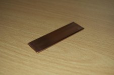
Bus-Bars
.............
COPPER PIPE
Do you know where I can get my hands on copper busbars?
.............
COPPER PIPE
Attachments

Dig These Curvey Bus-Bars Holmes ?
Simon......
copper busbars?...?
Simon......
Attachments
.............
COPPER PIPE
Something along these lines? I love free stuff!
Still confused about that star ground though!

Is that the Mars Rover?
Attachments
Simon......
I sincerely hope that amp has a glass cover cos it's always a shame to hide art away...
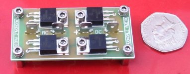
Rectifier Package ?
Just typed in CPC and got the Cambridge Pet Crematorium !
What component supplier is CHS ?
What are your rectifiers ?
Are they like this one ?
CPC...?
Just typed in CPC and got the Cambridge Pet Crematorium !
What component supplier is CHS ?
What are your rectifiers ?
Are they like this one ?
Attachments
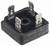
CHS is Charles Hyde and Son.
Yes my BR is the metal clad type, but I have was inspired by Avondale Audio to create my own as per attached...(full wave bridge rectifiers for audiophile hifi audio amplifiers from Avondale Audio : avondale audio)
Yes my BR is the metal clad type, but I have was inspired by Avondale Audio to create my own as per attached...(full wave bridge rectifiers for audiophile hifi audio amplifiers from Avondale Audio : avondale audio)
Attachments
Still confused about that star ground though!
Is that the Mars Rover?
Hi John
Yes I think it's the mars rover, pretty expensive RC car I reckon, can't get those in the shops.
The diagram looks great (apart from the nasty line fuse).
The best place for the star-ground is at the left of the middle bus-bar.
A bit of spare space maybe at the end of the bus-bar and a group of holes for the ground returns.
Maybe a few M3 for the low level returns.
And a couple of big ones for the speaker -'s (4 if you bi-wiring the speakers).
And a couple for the amp 0volt returns (could be quite big).
I like the wiring to be quite thick (but not welding cable!).
You could take your +&- volts for the amps from the left of the other bus-bar's as well.
I wondered if you have the rectifiers, and if they had spade terminals.
If they do depending on the size of the capacitors, its sometimes possible to drill small M3 or even M2 holes in the spade blades and screw them straight to the end of the bus-bars where the star ground holes are.
Its a bit extreme maybe, but they should have short thick wires to the bus-bars for best performance. My experience is that rectifiers in a 100w mosfet amp don't get all that hot relatively, if you have high current ones. As an alternative to screwing to bus-bars, thick wire (striped cooker cable is good), doubled up even, soldered to the rectifier tags is good for high currents and it has the fringe benefit of dumping any heat into the bus-bars when you tag and screw them down. Short as posible wiring for them anyway, if they are mounted up on the buss-bars and get hot you can always screw a bit of metal or sink to them up there.
I see your mates amp had some plastic film bypass capacitors on his reservoir capacitors ("Throw in a lousy buck you cheap b*^%$*d !") a few M3 holes along the bus-bars and its easy to mount them as well.
Good luck. This tape will self destruct in 5 seconds.

- Status
- This old topic is closed. If you want to reopen this topic, contact a moderator using the "Report Post" button.
- Home
- Amplifiers
- Power Supplies
- Dual PSU layout - how does this look?