Thanks Dave. I'll make that change. To me, the idea of actually cascading biquads is also a bit pitiful because that's wasting DSP resources.
How will you implement the mixed IIR/FIR mode? The most obvious way would be to simply give coefficients b0,b1,...,bM,a0,a1,...aN in a text file.
That would allow for the greatest flexibility.
Regarding OP amps I'm laying low with that for now. Much more important to get everything up and running.
/K
Nick, would it be possible to detect and reject a SPDIF signal that is not a proper stereo signal? I am taking a digital out signal from my AV processor. Under some conditions, this port can output a 5.1-format data stream. Via Najda, this comes through as either a motor-boating hiss (5.1 active) or a high-pitched sound (PVR paused).
Am I right when I say that the opamp next to the edge of the PCB is for channel 1 and 2?
According to the CS datasheet, two opamp are needed to feed the offset-ed differential input of the AD so the 2 eight pins opamp near to the edge are for inputs.
The other four are for outputs
Jean Claude
Yes,and wich one of them is channel 1-2?The other four are for outputs
Yes,and wich one of them is channel 1-2?
Well, have a look on the component side of the PCB, you can clearly see the traces leaving the input plugs...
Jean Claude
About the +/-12db filter gain. Is such high differences in gain not better addressed by other drivers or power amplifiers? There must be a considerable risk of clipping on the power amplifiers if You need a >24db correction. I might have misunderstood the discussion.
It's for filtering purpose that such a gain is required, not for level adjustment. For example a shelving filter with more than 12 dB of gain.
After a bit of work today all is properly encased and working perfectly.
Here she is all mounted up. The display slot took a while. Two 10mm holes and then careful jigsaw out. Rest was with various files, until I was satisfied. Fine emery cloth on file to finish.

To get the display flush I had to countersink it in the 8mm thick front panel.

This was done with lots of suitable depth 10mm drill holes and then angle grinder with flapper wheel to remove the rest.
Case feet

I decided I wanted the expansion board on the left as viewed from the rear. Plenty of space there.

Did you spot the mistake I've made in this shot?
Getting the holes in the right place took care.
Matches the MF unit - Could use some gold thoughand a nice Najda logo and text to indicate what the buttons and LEDs do...

Could do with a clean up not finished.
So very sucessful and the push to make buttons have a very nice action to them.
The 5mm hole for the IR works perfectly from the place I use the remote. Actually I just tested it and you can point the remote pretty much anywhere in the room away from the case and it still works!
Now - sit back and listen, with a nice cup of tea


Well, what can I say? That unit looks really good, Steve!!! Congrats and many thanks. I'd like to add a gallery on the website, and I'd like to include your machine.
I haven't spot the mistake you mentioned, but I can see there's no cut for the USB and Relay plugs.
I did a wooddenboard mount..
I use Salas shunregulators.
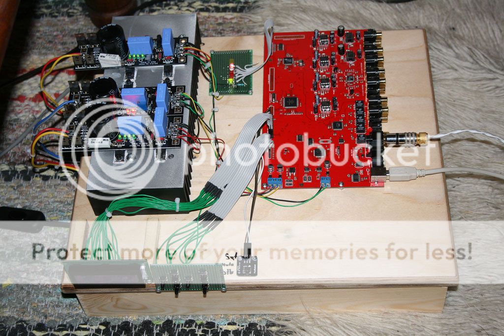
Today I have checked the digital input,and the Leds.
But I miss the abbility to invert the phase on each output..
Or is it there?
Yes it is there Forgott about it..
Very nice Ake, that's very serious work. Can I ask your permission to add this pic in the gallery as well? It shows the level of organisation which is required to achieve successfully the project.
(Anyone who wants to send me pics, please do so
)How will you implement the mixed IIR/FIR mode? The most obvious way would be to simply give coefficients b0,b1,...,bM,a0,a1,...aN in a text file.
That would allow for the greatest flexibility.
So I think we have agreed that the FIR/IIR mix would most likely consist in the FIR input processing tab combined to the IIR channel processing tab.
Regarding coefficients, this will be included in all IIR blocks, with the ability to load the content of a file. There will be these coefficient you mention, for biquad sections only - i.e. it's the user responsibility to decompose a higher order filter in second order sections.
Am I right when I say that the opamp next to the edge of the PCB is for channel 1 and 2?
No, the opamp for channels 1 and 2 is actually the 2nd from the left edge.
Nick, would it be possible to detect and reject a SPDIF signal that is not a proper stereo signal? I am taking a digital out signal from my AV processor. Under some conditions, this port can output a 5.1-format data stream. Via Najda, this comes through as either a motor-boating hiss (5.1 active) or a high-pitched sound (PVR paused).
We can look at this. There's a flag in the SPDIF streams that says whether it's PCM or something else. We could use this flag and zero outputs when it's not PCM. How about that?
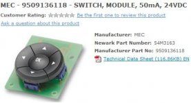
Regarding LCD wiring with the supplied flat cables, here's how I do it:

Basically the contacts come out of the housing so you can rearrange the order for your particular LCD pin out.
This works only if you don't require more cable length. Also, some of you have more elegant ways to wire the display - this is just a suggestion. (and no, this pic will def no go into the gallery
)So I think we have agreed that the FIR/IIR mix would most likely consist in the FIR input processing tab combined to the IIR channel processing tab.
Regarding coefficients, this will be included in all IIR blocks, with the ability to load the content of a file. There will be these coefficient you mention, for biquad sections only - i.e. it's the user responsibility to decompose a higher order filter in second order sections.
I'm not sure I follow here. I think of "Mixed FIR/IIR" as a generic filter transfer function:
H(z) = B(z^-1)/A(z^-1)
where A,B are polynomials in z^-1 and thus uniquely defined by the parameters b0,b1,...,bM and a1,a2,...,aN.
What would be the purpose of dividing this into biquads? Isn't is more efficient just to implement this is as a general filter structure from a DSP op count perspective?
I can understand the need for biquads as that is something people are used to and they certainly have their use. For maximum efficiency it would be nice to see the direct form implementation as well. I guess a check to see if all poles are inside the unit circle would also be great.
We can look at this. There's a flag in the SPDIF streams that says whether it's PCM or something else. We could use this flag and zero outputs when it's not PCM. How about that?
Sounds like a plan!
I'm glad to hear there's a likely easy fix.I'm not sure I follow here. I think of "Mixed FIR/IIR" as a generic filter transfer function:
H(z) = B(z^-1)/A(z^-1)
where A,B are polynomials in z^-1 and thus uniquely defined by the parameters b0,b1,...,bM and a1,a2,...,aN.
What would be the purpose of dividing this into biquads? Isn't is more efficient just to implement this is as a general filter structure from a DSP op count perspective?
In theory it would work, but you need astonishing word lengths to avoid quantisation errors and poles wandering around the plane. Let's look at the case of a 200 Hz LR4 at sampling rate 44100 Hz:
First coefficients for the second order Butterworth cascaded to perform the LR4:
1.989714 * 10^-4 * x[n- 0] +
3.979428 * 10^-4 * x[n- 1] +
1.989714 * 10^-4 * x[n- 2] /
-0.9605029194 * y[n- 2] +
1.9597070338 * y[n- 1]
4th order Bessel [1] direct form has coefficients:
[1] Not quite an LR4, but it's close enough to show the problem.
2.0265 * 10^-7 * x[n-0] +
8.1060 * 10^-7 * x[n-1] +
1.2159 * 10^-6 * x[n-2] +
8.1060 * 10^-7 * x[n-3] +
2.0265 * 10^-7 * x[n-4] /
-0.8738907598 * y[n- 4]) +
3.6141443803 * y[n- 3]) +
-5.6063792019 * y[n- 2]) +
3.8661223390 * y[n- 1]) +
Note the gain for the direct form is almost the square (remember, Bessel approximation) of the gain for each cascaded B2. Since each gain is a fraction of 1.0, that means your quantisation is worse for a direct form (much worse for low frequency filters).
I won't get into the poles going walkabout, but trust me, they drift into places you wouldn't want to visit without an elephant gun. Oppenheim & Schafer or Proakis & Manolakis each have a good treatment of coefficient quantisation effects.
I can understand the need for biquads as that is something people are used to and they certainly have their use. For maximum efficiency it would be nice to see the direct form implementation as well. I guess a check to see if all poles are inside the unit circle would also be great.
You'd spend way more time playing with extended-precision in direct-form than any savings from not computing multiple biquads. Besides, there are efficient ways of chaining multiple biquads -- although by the time you get to the point where you need that sort of speed, the thing is filtered beyond all recognition anyway.
Last edited:
Well, have a look on the component side of the PCB, you can clearly see the traces leaving the input plugs...
Jean Claude
Yeah,the traces go to the volumechip..
In theory it would work, but you need astonishing word lengths to avoid quantisation errors and poles wandering around the plane. Let's look at the case of a 200 Hz LR4 at sampling rate 44100 Hz:
...
I won't get into the poles going walkabout, but trust me, they drift into places you wouldn't want to visit without an elephant gun. Oppenheim & Schafer or Proakis & Manolakis each have a good treatment of coefficient quantisation effects.
You're quite right. It turns silly in a jiffy. I actually did dig out my old Proakis 2nd ed. Should probably get the 4th.
I think Nick hinted earlier that he's using double precision feedback but I'm not sure which filter implementation he's using. Anyway, if he's aware of the issue I'm sure steps are being taken. I found this pretty useful as well:
Filter coefficient quantization
Would it be possible to get a rough indication of performance at this point? The only thing I've heard so far is 120 biquads at 96kHz.
Is it even an option to have an expansion board with another DSP so there could be a natural L/R division?
Just thinking freely here, I have no immediate need.
/K
After reading chapter 8 in Digital Filters my understanding has greatly increased.
After reading chapter 8 in Digital Filters my understanding has greatly increased.
That looks like a really good book. Thanks for the tip!
Sounds like a plan!
Alright, I'll push this in with the next release.
I'm not sure I follow here. I think of "Mixed FIR/IIR" as a generic filter transfer function:
H(z) = B(z^-1)/A(z^-1)
where A,B are polynomials in z^-1 and thus uniquely defined by the parameters b0,b1,...,bM and a1,a2,...,aN.
What would be the purpose of dividing this into biquads? Isn't is more efficient just to implement this is as a general filter structure from a DSP op count perspective?
As DSP_Geek pointed out, you always decompose a higher order filter into second order sections.
Association of biquads can take various forms: cascade, parallel or any mix cascade/parallel.
In Najda, all biquads are cascaded. That's probably the most versatile.
I think Nick hinted earlier that he's using double precision feedback but I'm not sure which filter implementation he's using.
It's double precision in both feedforward and feedback paths. All coefs are 48-bit. Implemented structure of biquads is Direct Form 1.
Would it be possible to get a rough indication of performance at this point? The only thing I've heard so far is 120 biquads at 96kHz.
Is it even an option to have an expansion board with another DSP so there could be a natural L/R division?
Just thinking freely here, I have no immediate need.
/K
The hardware engineers at my previous dayjob daisy-chained a dozen DSPs to get more power (which the software guys ate up like kids at the candy store); after the first couple you're already in the Dark Lord's domain so you might as well keep going. Poor Nick, he probably didn't expect people would start asking for audio supercomputers
So very sucessful and the push to make buttons have a very nice action to them.
The 5mm hole for the IR works perfectly from the place I use the remote. Actually I just tested it and you can point the remote pretty much anywhere in the room away from the case and it still works!
Looks great, Steve.
I think I have the same buttons on order, are they from DFB Sound & Light Warehouse?
Just seemed to have a really nice and solid feel about them.
Hi all
I discussed this week-end with a great specialist of filters (I wont name as I am not sure I translate properly 100% his advice).
Basically, he told me
- below #200 Hz, pre-ringing from FIR maybe heard, so best to limit FIR above that threshold, most of the pre-ringing will disappear
- phase changes is mostly heard between #200 and #4000Hz, so it is nice to that phase is corrected in this range
Will this be compatible with the mixed FIR/IIR approach that has been discussed ?
BR
Jean-Louis
- Home
- Source & Line
- Digital Line Level
- DSP Xover project (part 2)