Well,
I have all the parts on order now except the case but I will wait with that until I have everything tested out. It's fibreboard until then.
I ended up ordering this display:
OLED Display
I'm waiting for the WaveIO board from Lucian as well which I will integrate via the I2S input so that's another datapoint for the I2S once I get it configured.
I have looked at this page:
OP amps
I'm tempted to just order some NJM4562's and be done with it since they are measured to actually perform better than the LM833.
Nick, would that be a drop in replacement?
Great to hear about the custom biquads since that's another requirement from my side.
That OLED looks cool... Op amps - ah the fun we have in store for us.
My case arrived from HK today.
I got them to pre-drill the holes for LEDs and push to make switches.
I have to cut out the LCD or Oled slot. I think a gold plated surround plate would look nice and bling and match my MF A3 CDP that I use as a transport...
All parts. Very nice construction and solid 8mm ali face plate...

Pre-drilled and switches sitting in

I have to drill the rear panel too. Gonna be working on this a bit this weekend.
Nice, the FIR/IIR mix will let me experiment FIR global phase correction !
Release expected beginning of May
")
JohnK had this to say;
"that depends of the design of the woofer system. For example, depending on which woofer is used and what the cut off frequency is, in one of my dipole woofer systems I need A Q PEQ boost of anywhere between 11 and 22dB. "
http://www.diyaudio.com/forums/multi-way/221948-nao-note-ii-rs-7.html#post3451218
Alright, I'll make 24 dB of gain available. And also up to -24 dB of attenuation in front of the filtering blocks so that you don't clip.
It seems a bit dangerous for less experimented users, who could be tempted to cascade a lot of gain locally - but on the other hand I don't want to limit others.
I have all the parts on order now except the case but I will wait with that until I have everything tested out. It's fibreboard until then.
That's interesting.I ended up ordering this display:
OLED Display
Note that there's no backlighting. So no connection and the backlight option in the menu is not applicable anymore.
There's also no contrast setting, you won't need that. Again, no connection and contrast menu option irrelevant.
Please let us know how it goes!
I'm waiting for the WaveIO board from Lucian as well which I will integrate via the I2S input so that's another datapoint for the I2S once I get it configured.
That's another interesting configuration. Looking forward to your feedback. So far we've tested Tenor and Amareno.
I'm tempted to just order some NJM4562's and be done with it since they are measured to actually perform better than the LM833.
Nick, would that be a drop in replacement?
I looked at the datasheet and it should be fine. Mind you: LM833 is not bad at all. I'd actually suggest that you first get used to the sound of the board with the supplied opamps, and only later try to upgrade because the change is going to be a rather subtle one I think (Hope you'll let us know).
I had tested a few opamps. I'll find the list again and I'll post it here.
Great to hear about the custom biquads since that's another requirement from my side.
Early May
I too started following this thread because I'm building a Nao Note and thought this would be perfect for it. I will definitely purchase one if it can be used for the Nao. Thanks.
No problem, changes are in the pipeline. Thanks for your interest.
They're talking about EQ corrections not level adjustments.
The shelving filters are limited (currently) to +/-12db gain, but you can cascade (add) sections to achieve dipole corrections (or whatever else) of greater than 12db.
If Nick were to change the software to allow >12db settings for the filters it won't improve the situation with regard to gain structure.....but it will make it a bit more straightforward to program......at least with the "free routing" scheme.
Cheers,
Dave.
Thanks Dave. I'll make that change. To me, the idea of actually cascading biquads is also a bit pitiful because that's wasting DSP resources.
I decided to do a little beautification project on the interior today. After wrestling the wires into neat packages the LCD was displaying weirdly. I checked the connections and gave them all a little love squeeze. All is back to normal. Nick, On the next board please make the numbers for the LCD linear. 1 thru 8 in a row and 9 thru 16 in the other. The LCD's I bought are all in a line and it's hard to assemble all those little connectors.
Love squeezes is all we need
Thanks for your feedback, and truth is that I had thought about it at some time.
The problem is that there's no standard for LCD pin out. Some display modules have the pins on 2 rows, just like Najda, and allow the use of a 1-to-1 cable. I think Shaun has such a display (Can you confirm Shaun?).
Hi Nick,
Thanks for all your hard work!
I have a question.
Are the outputs directly connected to the cs3318 or is the signal passing any of the opamps after leaving the analog volume control?
best,
Paal
Hi Paal,
CS3318 is the last stage before the output connectors.
Best,
Nick
My case arrived from HK today.
I got them to pre-drill the holes for LEDs and push to make switches.
I have to cut out the LCD or Oled slot. I think a gold plated surround plate would look nice and bling and match my MF A3 CDP that I use as a transport...
All parts. Very nice construction and solid 8mm ali face plate...
Pre-drilled and switches sitting in
I have to drill the rear panel too. Gonna be working on this a bit this weekend.
That looks great Steve!
 Really looking forward to the end result.
The 2 extra analogue outs will come on the Expansion Port 0 side of the board. Please reserve 5 cm on that side in your chassis if you want to fit the expansion board at same height level than the main board.
I can't wait to hear results of the OLED display. I recall reading on the Adafruit web site that they had to implement a software mod to make it compatible. It would be great to know that no such tweaks are required for this implementation.
Right. I posted about it here: http://www.diyaudio.com/forums/digi...sp-xover-project-part-2-a-60.html#post3404628.
That pin configuration does appear to be a standard of sorts; there are many (older?) displays that use that layout. It seems that most modern displays have serial interfaces. When I was searching for a brighter display, I looked for plasma (FLV) displays. They were quite rare and expensive. There were more 20x2 character displays than 16x2 types. I did come across one particular OLED display that seemed to be made as a plug-in replacement for the type I used, but none were immediately available at the time. OLED displays having the equivalent display area are typically smaller in overall size, so those may have been a special build.
I think if builders' search for suitable displays do uncover a current trend towards a common pin layout, it would be wise to report that here. We may be able to find a connectivity solution that benefits us all.
The problem is that there's no standard for LCD pin out. Some display modules have the pins on 2 rows, just like Najda, and allow the use of a 1-to-1 cable. I think Shaun has such a display (Can you confirm Shaun?).
Right. I posted about it here: http://www.diyaudio.com/forums/digi...sp-xover-project-part-2-a-60.html#post3404628.
That pin configuration does appear to be a standard of sorts; there are many (older?) displays that use that layout. It seems that most modern displays have serial interfaces. When I was searching for a brighter display, I looked for plasma (FLV) displays. They were quite rare and expensive. There were more 20x2 character displays than 16x2 types. I did come across one particular OLED display that seemed to be made as a plug-in replacement for the type I used, but none were immediately available at the time. OLED displays having the equivalent display area are typically smaller in overall size, so those may have been a special build.
I think if builders' search for suitable displays do uncover a current trend towards a common pin layout, it would be wise to report that here. We may be able to find a connectivity solution that benefits us all.
Hi,
I have not had any good sucess with room correction. I guess my knowledge is the limit
Paal
I don't want to start a polemical thread here but I still don't understand how you can correctly make Room correction above let's say to simplify 100 Hz or so... without changing massively the direct/reverberant ratio.
But I use a sharp IIR notch to remove the first main room mode successfully (27,8 Hz).
Anyway, Acourate should be exellent for making filters when Nick now introduces a FIR option.
Paal
Not sure I understand here, Najda already let you use FIR but of course with a reduced number of taps. This reduced number is the main reason why I suggested to Nick to introduce a mix FIR/IIR environment as you can use computer efficient IIR to bring a system close to an overall minimum phase device and apply global pre-phase correction with FIR.
Nick,
The upcoming software/firmware release with mix FIR/IIR and advanced biquad programming is a very good news !
Jean Claude
I don't want to start a polemical thread here but I still don't understand how you can correctly make Room correction above let's say to simplify 100 Hz or so... without changing massively the direct/reverberant ratio.
But I use a sharp IIR notch to remove the first main room mode successfully (27,8 Hz).
Not sure I understand here, Najda already let you use FIR but of course with a reduced number of taps. This reduced number is the main reason why I suggested to Nick to introduce a mix FIR/IIR environment as you can use computer efficient IIR to bring a system close to an overall minimum phase device and apply global pre-phase correction with FIR.
Nick,
The upcoming software/firmware release with mix FIR/IIR and advanced biquad programming is a very good news !
Jean Claude
You are probably right regarding room correction.
Regarding FIR, sorry I meant the combined FIR/IIR. Yes I know FIR is already available.
best,
Paal
Indeed. The lack of balanced output is the main reason I haven't gone for the Najda yet.
You could create one pretty easily.
Measure (or have Nick supply) the output resistance for the unbalanced connectors and an appropriate resistor could be wired from ground to the (-) output on an XLR (or other) balanced connector.
If the capacitance of the load and interconnect cables are within reason that should work well.
The lack of a balanced interface on the Najda board is actually a good thing since it simplifies the architecture and reduces cost.
Cheers,
Dave.
You could create one pretty easily.
Measure (or have Nick supply) the output resistance for the unbalanced connectors and an appropriate resistor could be wired from ground to the (-) output on an XLR (or other) balanced connector.
If it was that easy, I am sure Nick would have added that extra resistor as an option
If the capacitance of the load and interconnect cables are within reason that should work well.
I guess it is especially when those conditions don't apply that a proper differential output driver would be beneficial.
The lack of a balanced interface on the Najda board is actually a good thing since it simplifies the architecture and reduces cost.
Sure, but there are a lot of other things that could be done if simplicity and low cost were the main drivers.
Indeed. The lack of balanced output is the main reason I haven't gone for the Najda yet.
Same here
(I'd also like digital volume control)
If it was that easy, I am sure Nick would have added that extra resistor as an option
I guess it is especially when those conditions don't apply that a proper differential output driver would be beneficial.
Sure, but there are a lot of other things that could be done if simplicity and low cost were the main drivers.
It's not the extra resistors, but the suitable balanced connectors and pcboard real-estate required.
Since the Najda is just a circuit board and already requires some DIY effort to implement a working unit (mounting in suitable enclosure, wiring a 2x16 display, LED's, etc, etc), adding some chassis-mount XLR connectors to the construction should be straightforward.
In a domestic environment, I'm having trouble envisioning a situation where cable capacitance would not be within reason. Is your plan to run balanced interconnects to a source 100 feet away?
Cheers,
Dave.
In a domestic environment, I'm having trouble envisioning a situation where cable capacitance would not be within reason. Is your plan to run balanced interconnects to a source 100 feet away?
I am not sure my environment always qualifies as "domestic".
After a bit of work today all is properly encased and working perfectly.
Here she is all mounted up. The display slot took a while. Two 10mm holes and then careful jigsaw out. Rest was with various files, until I was satisfied. Fine emery cloth on file to finish.

To get the display flush I had to countersink it in the 8mm thick front panel.

This was done with lots of suitable depth 10mm drill holes and then angle grinder with flapper wheel to remove the rest.
Case feet

I decided I wanted the expansion board on the left as viewed from the rear. Plenty of space there.

Did you spot the mistake I've made in this shot?
Getting the holes in the right place took care.
Matches the MF unit - Could use some gold though and a nice Najda logo and text to indicate what the buttons and LEDs do...

Could do with a clean up not finished.
So very sucessful and the push to make buttons have a very nice action to them.
The 5mm hole for the IR works perfectly from the place I use the remote. Actually I just tested it and you can point the remote pretty much anywhere in the room away from the case and it still works!
Now - sit back and listen, with a nice cup of tea
Here she is all mounted up. The display slot took a while. Two 10mm holes and then careful jigsaw out. Rest was with various files, until I was satisfied. Fine emery cloth on file to finish.

To get the display flush I had to countersink it in the 8mm thick front panel.

This was done with lots of suitable depth 10mm drill holes and then angle grinder with flapper wheel to remove the rest.
Case feet

I decided I wanted the expansion board on the left as viewed from the rear. Plenty of space there.

Did you spot the mistake I've made in this shot?
Getting the holes in the right place took care.
Matches the MF unit - Could use some gold though
and a nice Najda logo and text to indicate what the buttons and LEDs do...
Could do with a clean up not finished.
So very sucessful and the push to make buttons have a very nice action to them.
The 5mm hole for the IR works perfectly from the place I use the remote. Actually I just tested it and you can point the remote pretty much anywhere in the room away from the case and it still works!
Now - sit back and listen, with a nice cup of tea
Last edited:
I ended up ordering this display:
OLED Display
Interesting! I have the same OLED lying around (but with different color), so I hope it works well with Najda! Keep us posted
I'll probably get my board during next week I did a wooddenboard mount..
I use Salas shunregulators.
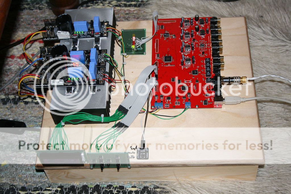
Today I have checked the digital input,and the Leds.
But I miss the abbility to invert the phase on each output..
Or is it there?
Yes it is there Forgott about it..
Nice to see!
Where did you get those flat cables with green wires? Or did you make them?- Home
- Source & Line
- Digital Line Level
- DSP Xover project (part 2)