Balanced is also about balancing impedances, not just to do with looking at differential signals
There are loads of references, so have a search
This can be used as a starter:
Balanced Interfaces
Have a look at the section The Balanced Interface
Thanks, I am pretty familiar with that stuff, having started out with exactly the balanced 600 ohm telecoms systems discussed in that document.
")
I stand by what I wrote - by far the most important part is the differential input stage at the receiver end. Yes, an unbalanced source does lead to a less-than-perfect common mode rejection ratio, but most people are more than happy with a fully unbalanced connection that has no common mode rejection at all.
Thanks, I am pretty familiar with that stuff, having started out with exactly the balanced 600 ohm telecoms systems discussed in that document.
Well you could probably have answered your own questions then
Well you could probably have answered your own questions then
The part I can't really explain to myself is the one where people would go through the trouble of adding an extra stage of active electronics or a transformer just to drive the connection. Yes, sure, if you are trying to drive a transmission line that is 25 miles long at high speeds, but for audio?
My experience of a lot of pro studio gear is that the "balanced" outputs of a lot of systems are really only normal unbalanced drivers connected to XLR connectors. There are of course exceptions, with proper, symmetric buffer circuits, but just because something has an XLR connector (and works with a balanced input) doesn't always make it truly balanced.
In regards to balanced vs pseudo balanced tomchr has performed some tests with his Audio precision system and the results are somewhere in his modulus-86 thread.
The true balanced setup gave a 90dB reduction in common mode interference whereas the pseudo balanced setup had 40 dB reduction. Purely unbalanced has no common mode interference rejection.
40dB reduction for free by using a properly wired cable seems to be well worth it.
I would tend to agree with Julf that in this case adding extra stages to balance the outputs of Najda would produce limited benefits and if not done very well could well do more harm than good.
If you are suffering interference problems from long cable runs or are trying to avoid ground loops by differential signalling then it makes sense.
The part I can't really explain to myself is the one where people would go through the trouble of adding an extra stage of active electronics or a transformer just to drive the connection. Yes, sure, if you are trying to drive a transmission line that is 25 miles long at high speeds, but for audio?
That's slightly different to the questions you were asking
If that's your question, then a few (potential) answers
- if done "properly" it shouldn't be an extra stage of active electronics but an alternative stage of active electronics. That seems fine to me
- the objective is simply to improve noise rejection on the interconnect. That can be valid in terms of traces on a PCB as well as anything longer. Designing in a balanced driver is comparatively straightforward, so to a great extent "why not?"
- personally I struggle with the concept of using a transformer, but then it's a relatively simple component that can provide controlled signal conditioning where an active circuit may be creating problems outside its intended operational range (open loop gain response vs. feedback loop)
- This is DIY - the people round here will go to the lengths they deem appropriate and they're free to do that
My experience of a lot of pro studio gear is that the "balanced" outputs of a lot of systems are really only normal unbalanced drivers connected to XLR connectors. There are of course exceptions, with proper, symmetric buffer circuits, but just because something has an XLR connector (and works with a balanced input) doesn't always make it truly balanced.
Indeed. That, I believe, is why some of the others here were asking about implementing a "proper" balanced output.
- if done "properly" it shouldn't be an extra stage of active electronics but an alternative stage of active electronics. That seems fine to me
Indeed, if the output stage is designed to be balanced from the start that is definitely the optimal solution. My point is that if it isn't, there is really no point in adding an extra stage (or transformer).
Absolutely.the objective is simply to improve noise rejection on the interconnect. That can be valid in terms of traces on a PCB as well as anything longer.
I agree, and I have never understood why hi-fi manufacturers don't do balanced by default (as is the case in the pro world).Designing in a balanced driver is comparatively straightforward, so to a great extent "why not?"
Of courseThis is DIY - the people round here will go to the lengths they deem appropriate and they're free to do that
- but I think this is also a place to discuss the rationale of different solutions.Anyone considered this for single ended to balanced conversion of Najda output?
Are there other good alternatives?
ghentaudio --- RTX (unbalnced RCA to balanced XLR) Module
Hi,
I did my own iteration a while ago already with the That 1446 and it is working great
JC
Attachments
Anyone has experiences with USB to I2s boards and Najda?
1) What board can you recommend?
2) Anyone tried DSD files with an USB to I2S board ? Does it make sense as Najda is downsampling?
3) JC do you have some boards left for the conversion to balanced? Or are you making another charge. I would be interested! ;-)
... as well in a dxf / CAD file for your 1 unit cabinet and the nice switch on the front
Thank you for your help!
Kind regards
Christian
3) JC do you have some boards left for the conversion to balanced? Or are you making another charge. I would be interested! ;-)
... as well in a dxf / CAD file for your 1 unit cabinet and the nice switch on the front
Kind regards
Christian
MP sent
JC
Nick. I have myself a najda now. yay .
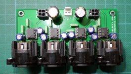
Can you tell me which opamps are matched to which outputs? also can you tell me what the 4 electrolytic caps are for sitting around each opamp?
I have installed some burson opamps but initial impressions weren't good. Needs some burn in I expect.
Regards
Simon
.Can you tell me which opamps are matched to which outputs? also can you tell me what the 4 electrolytic caps are for sitting around each opamp?
I have installed some burson opamps but initial impressions weren't good. Needs some burn in I expect.
Regards
Simon
Especially this part:
MYTH: MOST OP AMPS ARE COMPATIBLE - Op amps are complex devices. While many have the same pin configuration making it appear you can simply substitute one for another, that’s often not the case. They’re optimized for different input bias values, configurations, gains, feedback circuits, load impedances, quiescent currents, speeds/bandwidths, compensation values, operating voltages, noise trade-offs, etc. But some audiophiles can’t be bothered by, or don’t understand, all those details. So they simply swap them out without changing anything else in the circuit. Many have a favorite op amp or two they like to use in most everything without considering if it’s a good match. It’s like the old quote “when you have only a hammer everything looks like a nail”. But that just doesn’t work for op amps. And, not surprisingly, some op amps do better than others when you ignore their requirements. Again, this is a lot like the Second Grain Of Truth above. If you use a given op amp incorrectly, it may well sound different. But it’s not the op amp’s fault. The person misusing it is creating the audible differences.
MYTH: OP AMP UPGRADES ARE USUALLY WORTHWHILE - The forums are full of posts from people who buy some perfectly nice piece of audio gear, open it up, discover the manufacture used a “cheap 5532” op amp, and they promptly pop in something much more expensive and exotic to “improve the sound”. These are usually people who lack the test equipment to have any idea if their op amp swaps help, hurt, or are just a waste of money. They simply use their ears, in highly biased sighted listening, and draw all sorts of erroneous conclusions. I know of op amp swaps causing potentially harmful oscillation. Someone might hear ultrasonic artifacts from the oscillation as “newfound detail” when, in reality, they have unwittingly created a radio transmitter. And this isn’t as rare as you might think because of the “faster is better” mentality.
Nick. I have myself a najda now. yay
Can you tell me which opamps are matched to which outputs? also can you tell me what the 4 electrolytic caps are for sitting around each opamp?
I have installed some burson opamps but initial impressions weren't good. Needs some burn in I expect.
Regards
Simon
Maybe I should have removed the last couple of sentences.
Hi Nick
After using Nadja DSP since Januar and made a lot with FIR config with some quality tweeter:
Ss9900
Ss6640 Be
Mundorf AMT
HIVI RT2H
Visaton KE25
I am also really interested what the new board can do?
I WISH really Decimation or other spreading/allocation of FIR Taps.
Tweeter needs not just about the have of 500 of to the less limited channels of Nadja and Bass/Mid should get all the rest...
I really like this Nadja board so much!
PS: Dont waste your time with changing DAC/Opamps and change there where it really change....
Can you tell me which opamps are matched to which outputs? also can you tell me what the 4 electrolytic caps are for sitting around each opamp?
I'll add this to the documentation, as it has been asked quite often.
- Looking at the board with power terminals on the right side, then left to right the opamps are for ch. 3&4, ch. 1&2, ch. 7&8, ch. 5&6.
- The 2 upper capacitors are coupling the audio signal out, that's the ones you're looking for.
I am also really interested what the new board can do?
I WISH really Decimation or other spreading/allocation of FIR Taps.
Tweeter needs not just about the have of 500 of to the less limited channels of Nadja and Bass/Mid should get all the rest...
I indeed have a new hardware revision coming out soon. The reason is that the combo RCA/toslink I used on the previous boards is not available anymore, that was a real bugger.
The new board will feature one extra toslink output and DIP switches for selecting analogue input level (1 Vrms or 2 Vrms), as well as a few marginal improvements.
Decimation will be introduced with the new NUC, compatible with all boards.
Decimation will be introduced with the new NUC, compatible with all boards.

Decimation will be introduced with the new NUC, compatible with all boards.
Nice!
Couple of questions:
1. You mentioned earlier that the 8500 taps could be freely distributed between channels. Will this be implemented with the new NUC revision?
2. Are there limitations to the decimation factor that can be used?
3. Looking at the data sheet of the CS42428, it appears to have differential audio outputs. For us using Hypex amps with 100k input impedance and DC caps, would it be possible to go directly from the differential outputs of the dacs to the hypex amps? If so, would you consider adding traces and holes in the new revision for differential outputs?
- Home
- Source & Line
- Digital Line Level
- DSP Xover project (part 2)