I'm trying to get i2s playback using an RPi or a BBB. When I enable the Exp1 input, by grounding pin 13 to pin 10, I can select Exp1 in the NUC user interface.
But, as soon as I select Exp1, the left and right inputs skyrockets, even though there is nothing connected on the i2s pins (1, 23 and 25).
Is my Najda i2s toast? If not, what am I missing here?
BR,
/Bo
In my case...
If I just ground pin 13 and 10 I have, as you say skyrockets on one channel...
but when I connect i2s pins form rPi everything is fine...
so you haven't tost DSP...
but I have one problem with rPi and Najda...
from time to time, I get skyrocket on one channel, and it's not nice when you here that on tweeter at listening levels...
I'm afraid to destroy tweeter that way...
In most cases it happens when I press ''next'' song via ''volumio'' on rPi...
than I get ''skyrocket'' and music continues to play, but one channel get stacked at skyrocket mode with nasty skwiking sound...
than I have to restart everithing...sometimes I have to do that couple times before everything gets back to ''normal''
I belive that DSP louse connection with rPi ?
Will try ''rune audio'' instead ''volumio''...
I am having trouble getting the rotary encoder to work. I am using the front panel board, everything else on that is working fine. I have set the volume setting to wheel and connected to pins 12 and 14 on expansion port 1 but I get no response from the encoder. I have tried reversing the connections to pins 12 and 14 this made no difference. The mute switch part works fine though. I put a multimeter across the two pins from the front panel board but moving the encoder doesn't seem to register. Any ideas on a way to find out what the issue is? The encoder is a bourns pec 11r.
When I have the encoder working I will post some pics of the finished article, I am very happy with how it has turned out.
When I have the encoder working I will post some pics of the finished article, I am very happy with how it has turned out.
I am having trouble getting the rotary encoder to work. I am using the front panel board, everything else on that is working fine. I have set the volume setting to wheel and connected to pins 12 and 14 on expansion port 1 but I get no response from the encoder. I have tried reversing the connections to pins 12 and 14 this made no difference. The mute switch part works fine though. I put a multimeter across the two pins from the front panel board but moving the encoder doesn't seem to register. Any ideas on a way to find out what the issue is? The encoder is a bourns pec 11r.
When I have the encoder working I will post some pics of the finished article, I am very happy with how it has turned out.
What I can think of is the following:
- Check the pins on Expansion Port 1 where you've plugged the encoder. Both pins should be on the row near the PCB edge.
- Have you assembled the additional parts as well? (2 resistors and 2 capacitors)
Looking forward to your pics!
Nick
When you complete a new project ?
H Michyy,
There's no new DIY project in the pipeline. The plan is rather to improve the existing system.
Cheers
Nick
Fixed
Hi Nick,
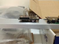
All working now, the information about the location of the pins helped, didn't realise it was odd on one side even on the other. When connected to the right pins everything is spot on.
Here is a quick and dirty picture, I'll take some better ones in natural light and post them
Thanks
Hi Nick,
All working now, the information about the location of the pins helped, didn't realise it was odd on one side even on the other. When connected to the right pins everything is spot on.
Here is a quick and dirty picture, I'll take some better ones in natural light and post them
Thanks
Attachments
Here is a quick and dirty picture, I'll take some better ones in natural light and post them
Hi, it looks like you have selected the slimline 1U 10 mm front panel, 280 mm deep Modushop cabinet.
I plan myself to build in the near future, when time will permit, another Najda in this cabinet. As I would like to draw this cabinet in my CAD software and as Modushop is not very clear on some dimensions, I would really appreciate some informations :
1) 10 mm front panel, the length is 450 mm but was is the exact height ?
2) I understand that the front panel is maintained to the side panel by some pièces of aluminium, could you share the dimensions ?
3) if you have selected the 3mm aluminium cover too, could you confirm position/ location/number of air holes ?
Thanks in advance
Jean Claude
Hi Jean-Claude,
There is a group buy thread for a 1U/2U case, arranged by Ardi and with input from Nicolas. Hopefully it is close to taking off.
Any more takers?
http://www.diyaudio.com/forums/digital-line-level/242413-dsp-xover-najda-panels.html
There is a group buy thread for a 1U/2U case, arranged by Ardi and with input from Nicolas. Hopefully it is close to taking off.
Any more takers?
http://www.diyaudio.com/forums/digital-line-level/242413-dsp-xover-najda-panels.html
There is a group buy thread for a 1U/2U case, arranged by Ardi and with input from Nicolas. Hopefully it is close to taking off.
Any more takers?
Thanks for the input, but I'm the kind of guy that prefer to have one that will fit exactly my need (I have one Najda with symmetrical inputs/output in a 2U case but I plan the next one in 1U, OLED display, external reference clock, analog expansion board, JLSounds USB buffered input, AC filtered plug and mixed SMPS/linear regulators...
Best from France
Jean Claude
May I introduce myself ...
... to this noble circle of Najda owners?
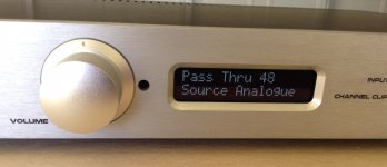
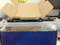
Just yesterday night I rigged up my Najda, took me not more than 2 hours to make it functional. For now I'm enjoying it's upsampling abilities in SPDIF pass through mode. My concern was that uneven upsamling ratios could compromise sound - but au contraire: Nothing to blame, bass gets deeper (huh?) and tighter. Anything else seems unchanged.
Now I have to go over this thread with a toothcomb to figure out how to make a 3 way crossover out of it ... Or is there some tutorial in a "How to teach a pygmy to fly a spaceshuttle" style?
Regards,
Gerd
... to this noble circle of Najda owners?
Just yesterday night I rigged up my Najda, took me not more than 2 hours to make it functional. For now I'm enjoying it's upsampling abilities in SPDIF pass through mode. My concern was that uneven upsamling ratios could compromise sound - but au contraire: Nothing to blame, bass gets deeper (huh?) and tighter. Anything else seems unchanged.
Now I have to go over this thread with a toothcomb to figure out how to make a 3 way crossover out of it ... Or is there some tutorial in a "How to teach a pygmy to fly a spaceshuttle" style?
Regards,
Gerd
Attachments
![IMG_2831[1].jpg](/community/data/attachments/413/413740-f13f1a4f226a768bd829bba30a96107b.jpg)
Sounds nice Jean Claude.
Gerd, I do not think you need to look through the thread. The NUC manual is on the website;
WAF-Audio
Here are some ideas to get started quickly; To balance the DSP load, use 1,2,3 for left, 6,7,8 for right (see page 14). Skip to page 16 for an example crossover. Go to file and "add output graph tab", tick the channel boxes, and you will see the graph of your progress (page 24).


Jean Claude,
Yes you are right Modushop 10mm front panel in 1U 280mm deep.
Here is some information for you I have attached the pdf of the drawings to modushop
This is the link to the basic CAD drawings on their site
Hi-Fi 2000 contenitori per l'elettronica, case modding HTPC, Galaxy, rack, DIYaudio, computer cases, front panel express, knobs,milled Handles, milled fronts, hi-end,
The panel is held on by metal L brackets they are 35mm long on the sides and 10mm long on the front, the holes marked on the edge of the panel pdf show where these are.
Send me a PM with your email if you want the autocad version so you can check any dimension
I'll post more pictures later when I get a chance so this might make more sense then.
Attachments
Photos
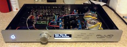
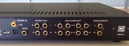
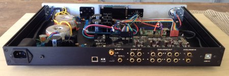
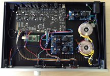
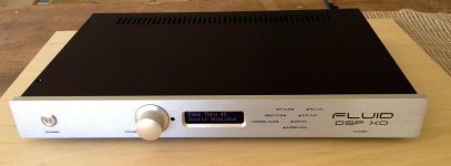
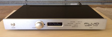
As promised some better photos these are the finished enclosure. Linear power supply, front panel board cut up and moved around, and an Amanero which has yet to be set up.
I'm very happy with the outcome, modushop did a really good job with the machining and I can recommend them.
As promised some better photos these are the finished enclosure. Linear power supply, front panel board cut up and moved around, and an Amanero which has yet to be set up.
I'm very happy with the outcome, modushop did a really good job with the machining and I can recommend them.
Attachments
-
 IMG_0066.jpg456.2 KB · Views: 285
 -
 IMG_0065.jpg494.3 KB · Views: 287
 -
 IMG_0064.jpg512.4 KB · Views: 319
 -
 IMG_0063.jpg859.1 KB · Views: 320
 -
 IMG_0062.jpg430.2 KB · Views: 219
 -
 IMG_0061.jpg588.5 KB · Views: 243
 -
 IMG_0060.jpg539 KB · Views: 525
 -
 IMG_0059.jpg474.5 KB · Views: 556
 -
 IMG_0058.jpg392.9 KB · Views: 620
More photos
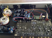
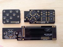
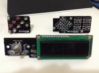
Theses are some photos of the front panel being constructed
They show where I cut the front panel into pieces to fit where I wanted them.
I am using the keypad section as a spare so I can use it to change the setup later if need be. For now everything works via remote control.
I used a thin kerf japanese saw and it was easy to cut the board up and left a neat finish. I bought the wrong size switches, I bent the legs and soldered them in place and they work fine, especially as they are only a setup tool for me.
Attachments
Jean Claude,
Send me a PM with your email if you want the autocad version so you can check any dimension/PM sent
thank you very much
Jean Claude
Jean Claude,
Yes you are right Modushop 10mm front panel in 1U 280mm deep.
Here is some information for you I have attached the pdf of the drawings to modushop
This is the link to the basic CAD drawings on their site
Hi-Fi 2000 contenitori per l'elettronica, case modding HTPC, Galaxy, rack, DIYaudio, computer cases, front panel express, knobs,milled Handles, milled fronts, hi-end,
The panel is held on by metal L brackets they are 35mm long on the sides and 10mm long on the front, the holes marked on the edge of the panel pdf show where these are.
Send me a PM with your email if you want the autocad version so you can check any dimension
I'll post more pictures later when I get a chance so this might make more sense then.
I have now all the necessary information. The only missing one is for the ventilation holes on cover. It seems, according to the very nice pictures taken a few post below that there is only one row instead of two. If you can give the position of the first and last ventilation holes relative to the sides and back of the cover, I will be able to draw everything correctly.
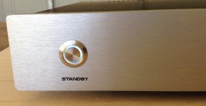
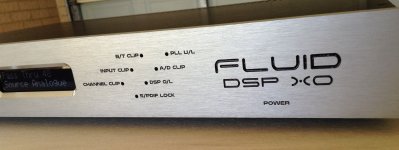
Again, congratulation for this very nice build. I like also the very nice engraving.
Jean Claude
Jean Claude,
Dimensions for the hole cutouts are 52mm from left/right edges and 25 from back in my pictures the slots themselves are 30mm long and 2mm wide, the slots can be either on the front or back edge they fit either way.
Thanks for the nice comment on the engraving.
Dimensions for the hole cutouts are 52mm from left/right edges and 25 from back in my pictures the slots themselves are 30mm long and 2mm wide, the slots can be either on the front or back edge they fit either way.
Thanks for the nice comment on the engraving.
- Home
- Source & Line
- Digital Line Level
- DSP Xover project (part 2)