I checked calculation load again,
Now I "skip" 64 for 44100, 32 for 88200 in FIR routine, because I insert 0 for oversampling.
So Total calculation for FIR = 2.8MHz * (2048 / 64 +7) = 2.8MHz * 32 operation
IIR = 2.8MHz * (16 + 7) = 2.8MHz * 23 operation. not a much difference.
(IIR infinitely remains effect of previous calculation, so I cannot skip.)
Last edited:
FIR LPF is, making pre - post "echo" from one sample data, then summarize for whole echo on each sample.
(a) x0,0,0,0,........x64,0,0,0,0,0.... -> LPF -> multiply 64 = y0, y1, y2.... y64,y65...
(b) linear interpolation from x0, x64 -> x0, x1, x2, ..... x64, x65,..... -> LPF = y0,y1,...
at (a), y1-y63, y65-y127 are generated by smooth sync() function. and original y0, y64 points are re-generated, no changes happen.
at (b), "linear" means not smooth, that is angular. you will add some high frequency signal to the original. this signal will effects final y0, y64.
(a) insert 0: no additional signal.
(b) interpolation: "linear interpolating" signal is added, then LPFd.
for example.. difficult.
Original, Triangle wave. 44.1kHz sampled, so peak was cut.
(a) suppose nothing, just let summarize of sync() function of pre-post points.
(b) suppose "flat top". when it goes to LPF, flat top signal will cause undesirable ringing.
Well, is debatable if that is trully better that linear. Sure, is better for pure sinusoidal signals, but music is seldom sinus.
I guess it needs to be tested")
Hey, I have one ideea - why stick to 2.8224 MHz? Let the 48 and 96 generate the higher signal (x64 or x32 give 3.072 MHz) - you are not using a regular DAC anyway after that, so it will not be a problem!
PS: Even for a regular DSD DAC, that difference should not be a problem.
I guess it needs to be tested
Hey, I have one ideea - why stick to 2.8224 MHz? Let the 48 and 96 generate the higher signal (x64 or x32 give 3.072 MHz) - you are not using a regular DAC anyway after that, so it will not be a problem!
PS: Even for a regular DSD DAC, that difference should not be a problem.
Last edited:
X128 - the most usable
Currently, from a lot of rec. eng. who use Korg MR2000S DSD recorder, The most usable mode is X128 for all new recordings storage format.
Sound-vise I prefer it also.
To all, who already DL . . would be in the need . . .
Regards
Hey, I have one ideea - why stick to 2.8224 MHz?
Currently, from a lot of rec. eng. who use Korg MR2000S DSD recorder, The most usable mode is X128 for all new recordings storage format.
Sound-vise I prefer it also.
To all, who already DL . . would be in the need . . .
Regards
There are some Upsampler, which make fake high-frequency more than 22k.
Someone like it, but I want to keep original sampled value in PCM.
I will take a screenshot, to show how actual music signal is processed at oversampling and LPF.
Yes I don't care DSD frequency, but making 3.072MHz DSF file is only for me at now
Player, Driver, DDC, DAC or AMP, every component have to be aware of 2.822/3.072 (and 5.644/6.144) MHz DSD can exist.
My new DDC has both 44100/48000, so I can try on next version. I will receive parts box from Digikey today.
I thought that there is no point of MAKING a DSD file... The analog reproduction of PCM via a 1 bit converter (DSD) was the original intent, no? With live conversion...
For that intent, there is no difference in what frequency the resulting "DSD" actually is.
Not messing with unrelated bitrate changes (44.1 to 48) always yields better audio results.
For that intent, there is no difference in what frequency the resulting "DSD" actually is.
Not messing with unrelated bitrate changes (44.1 to 48) always yields better audio results.
Thanks!Regards
Last edited:
Hi Sonic, This thread is titled "DSF Player + ...", playback DSF file as it is, is original.
on the fly PCM-DSD-output is applied usage. (more difficult, than offline conversion)
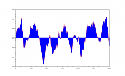
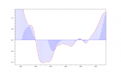
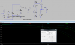
Attached, actual music file in process.
Blue shows original PCM + 63 of zero.
Red shows FIR LPFed signal, 1024 offset.
you can see Red line traces Peak point of Blue (PCM oroginal sample point) very faithfully, in limited bandwidth (<22050).
To see these plot,
(1) edit //debug file dump// area in the loop, then build my program
(2) run Scilab, type
M = fscanfMat("c:\temp\FIR_IN.txt");plot(M);
n = fscanfMat("c:\temp\fir_out.txt");plot(n, '-r');
I can not debug this program without Scilab.
on the fly PCM-DSD-output is applied usage. (more difficult, than offline conversion)
Attached, actual music file in process.
Blue shows original PCM + 63 of zero.
Red shows FIR LPFed signal, 1024 offset.
you can see Red line traces Peak point of Blue (PCM oroginal sample point) very faithfully, in limited bandwidth (<22050).
To see these plot,
(1) edit //debug file dump// area in the loop, then build my program
(2) run Scilab, type
M = fscanfMat("c:\temp\FIR_IN.txt");plot(M);
n = fscanfMat("c:\temp\fir_out.txt");plot(n, '-r');
I can not debug this program without Scilab.
Attachments
Last edited:
DSD X128 - Live recorded
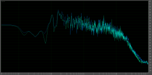
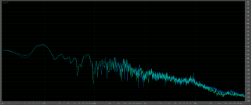
Here is a FC charactereistic from a Live Piano recording made in DSD X128, invented by Mr. Koji Oishi and made available by Korg
Img. 1. the recorded spectra is all the way till 60 KHz, physical limit of the Mics,
Img. 2. the mics phantom Pw. is switched off, so is the only noise from mic pres on the graph.
Tipical fraquency characteristic from the DSD X128 recorder.
Img. 3. the Sony invented 12" optical disc -DAD to replace LP Record . .
Just for the info how high the supersonic informations exist from playing 2. Steinway pianos. If this file is converted to CD Fs. with the best converter money can buy. . . the 2. Steinway grand pianos become unknown brand with disappeared feeling of the live event - the life-like magic - everything is gone . . . and it is really sad to know that even today more than 70% of all quality music is still recorded at a miserable (Sony) Mr. Ogha chosen in the 1979 a 16 bit and 44100 KHz Fs resolution. Since then, after they "kill" the LP record, the music recorded digitally was made a big step back in persevering supersonic informations and make it "digitally-sterile" till the today time, this way "they kill" a no reversed quantity of music which were recorded till today in that "Sterile" life-less standard. Thank good to "not-deaf" people at Toshiba who go in a war against the "DEAF" zombies at Sony and establish a new DVD-Audio disc them self with a Higher Fs of 192KHz-24bit LPCM and this way open the Eyes and Ears to the whole world that there actually is the needed for "super-sonic higher resolution" for music recording and playback to preserve as much as possible in the reality existed Life-like fell in music over 20 KHz "no one actually able to hear" ?? (and lose the war again with the Sony), but since then the world move further and being no more default "DEAF" to ones belief. . . so if this higher-sonic informations are also present in the playback, It LOSE (the music) that STERILE feel and become more like it is in a real life-like event while happening on the stage within the concert.
Regards
Attachments
Correct.Hi Sonic, This thread is titled "DSF Player + ...", playback DSF file as it is, is original.
on the fly PCM-DSD-output is applied usage. (more difficult, than offline conversion)
What I meant to say is that you can play the regular DSD files (with 2.8MHz) and the converted PCM (at 2.8 or 3.0 MHz, depending of the PCM source).
There is no need to suplementary convert the 48 or 96 kHz PCM to 88.2 kHz PCM before DSD conversion (to get the standard 2.8Mhz DSD).
Now, to try to create DSD files from 48kHz and 96kHz PCM, that is IMO pointless. There is no quality gain from that - files should stay as recorded.
OK guys, to realize live sounding 5.6M/6.14M DSD playback system..
good news:
(1) my program has "coefficient calculator" inside, so FIR LPF and 7th noise shaper are, adaptive. sampling rate, oversampling rate, are just a parameters in the program.
(2) now USB DDC(I2S/DSD) 2nd version is on my desk, to be soldered. it has FT2232H / IDT FIFO / 74HCxxx / Power, Clock, everything DIP device. will handle 44.1/88.2/48/96/2.8M/3.07M/5.6M/6.14M.
(3) parts for DSD amp(just a high speed transistor amp) arrived in DigiKey box.
bad news:
too many things to do
USB DDC, DSD amp are under construction and I'm not sure the amp can process 6MHz.
prototype PCM to DSD converter have to be blushed up for Hi-res, and implemented into on-the-fly DSD converter, into ASIO driver.
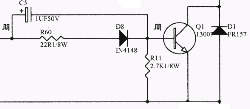
Hi SoNic, The DSD amp is constructed by..
(1) some bits parallel in + DSD signal -> AND gate -> R-2R = voltage controlled digital pulse.
(2) emitter follower (1 tr)
(3) base common amp (1tr), voltage multiply 5.
(4) emitter follower (4 tr)
If it doesn't work, I will try Radio amplifier.
Is this an Analog Amp? or Digital Amp?
Every Tr get 2.8MHz 1 or -1 pulse and work, and they are not aware of "level of music signal at now".
Attachments
If it doesn't work, I will try Radio amplifier.
Awesome, direct 1bit stream at 5,6 MHz, and possibility to form the active speaker system, skipping many inter-stage manipulating - conversion processing just pure Hi-Res direct playback. . .
Hardly waiting for the first impressions . . .

1. You don't have the dead time implemented.
2. I thought you will use some IRF540N - probably they can handle 4 MHz switching. With 40ns dead time.
3. The bipolars might be slow to switch when you drive them to saturation like that (with a resistor). Below is what is usually done for switching bipolars in switched power supplies.
2. I thought you will use some IRF540N - probably they can handle 4 MHz switching. With 40ns dead time.
3. The bipolars might be slow to switch when you drive them to saturation like that (with a resistor). Below is what is usually done for switching bipolars in switched power supplies.
Attachments
Hi I already did switching version, and implemented dead-time control.
But I had audible white noise when I'm close to speaker.
I found noise current on GND line, maybe I need plate GND to eliminate switching pulse noise. But I feel disgusting
The circuit itself is designed for MHz amplification. LTSpice shows over 20MHz response.
I don't have spice model for MJE200/210, but final stage has no gain, not so bad, I hope.
Attachments
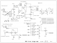
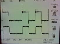
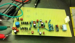
OK I made non switching DSD AMP! ....for, headphone now
attached, final stage output, and board photo.
CH1: FPGA output, CH2: Emitter output
MJE200/210 was too slow. So I made 4-parallel output stage by 2N3904/3906.
This circuit (parallel small Tr) is used for DIY ham radio, so can work for 7MHz application.
Next I will make 0.1W/pair x 32 = 3.2W amplifier.
Signal is very clean everywhere.
Attachments
- Status
- This old topic is closed. If you want to reopen this topic, contact a moderator using the "Report Post" button.
- Home
- Source & Line
- Digital Source
- DSD Playback system, DSF Player + USB DDC + DSD Amplifier